This proposed change addresses the transfer of loads between the roof structure and braced wall panels.
Problem
The requirements in Sentence 9.23.13.5.(3) of the 2025 edition of the National Building Code of Canada (NBC) regarding the transfer of lateral loads from roof framing members to braced wall panels are unclear and have created confusion within the truss industry. The intent of the existing Sentence is to ensure that stronger wall types (WSP‑B or higher) can effectively transfer lateral loads to and from the roof structure. However, the requirements and figures in the associated explanatory Note do not clearly illustrate how blocking elements should be constructed or connected, nor do they provide sufficient information on the design loads that blocking elements must resist or clarify the differences between partial‑ and full‑height blocking configurations.
Improper or inconsistent blocking can result in inadequate lateral load transfer, truss rotation, or damage to truss connections, potentially reducing the building’s ability to resist wind and seismic forces. The lack of clarity can also create uncertainty among designers, builders and truss manufacturers regarding how to design and apply blocking details. Inconsistent interpretation resulting from these gaps may lead to construction quality issues and non‑compliance with the intent of the requirements, posing safety concerns.
Clarifying this requirement is necessary to ensure consistent, safe and constructible methods for transferring lateral loads from roof structures to braced wall panels, while maintaining the prescriptive nature of Part 9.
Justification
This proposed change clarifies the current requirements for transferring lateral loads from roof structures to braced wall panels and expands on them by directly addressing the missing technical detail and risk of inconsistent interpretation identified in the current provisions. The new Article9.23.13.6. and its accompanying tables establish prescriptive requirements for solid blocking, blocking panels and engineered truss panels, including their construction, materials and fastening details. These proposed revisions are intended to resolve confusion about how blocking elements should be constructed and connected, thereby reducing the likelihood of improper load transfer and limiting the probability of damage to roof components.
This proposed change introduces consistent fastening patterns and acceptable materials (such as solid lumber or structural composite lumber), and references venting provisions for full‑height blocking to maintain attic ventilation. By referencing the factored shear resistance values in new Table9.23.13.6.‑C, this proposed change specifies that blocking or truss panels must meet or exceed the strength of the braced wall panel below, which addresses the uncertainty about load capacity and would improve reliability in lateral load transfer. Clear differentiation between full‑height and partial‑height configurations—including specific fastening requirements and minimum gaps for partial‑height blocking—would reduce confusion in application and limit the probability of inadequate load paths or truss movement. Collectively, these clarifications provide a consistent prescriptive method that supports safe, practical and verifiable roof‑to‑wall load transfer practices.
Implementing this proposed change at the National Model Code level is the most effective approach to resolve the problem that originated in the wording of the NBC2025 and affects prescriptive construction practices. This proposed change promotes the consistent interpretation of the requirements for transferring lateral loads from roof structures to braced wall panels and their application where the National Model Codes are adopted by provincial and territorial authorities. This proposed change also limits the probability of unsafe conditions under wind and seismic loading, and maintains the prescriptive intent of NBC Part9 while improving clarity, consistency and constructability.
PROPOSED CHANGE
[9.23.13.] 9.23.13. Bracing to Resist Lateral Loads Due to Wind and Earthquake
(See Note A-9.23.13.PROPOSED CHANGE A-9.23.13.)
[9.23.13.1.] 9.23.13.1.Requirements for Low to Moderate Wind and Seismic Forces
[9.23.13.2.] 9.23.13.2.Requirements for High Wind and Seismic Forces
[9.23.13.3.] 9.23.13.3.Requirements for Extreme Wind and Seismic Forces
[9.23.13.4.] 9.23.13.4.Braced Wall Bands
[9.23.13.5.] 9.23.13.5.Braced Wall Panels in Braced Wall Bands
[1] 1)Except as provided in Sentences (2)and 9.23.13.12.(2)to (4), and Article 9.23.13.9., braced wall panels shall
[a] a)be located within braced wall bands,
[b] b)be laterally supported at each floor level and the roof,
[c] c)extend, as applicable, from the top of the supporting footing, slab or subfloor to the underside of the floor, ceiling or roof framing above, and
[d] d)conform to the spacing and dimensions given in Table 9.23.13.5. and Article 9.23.13.9.
Table [9.23.13.5.] 9.23.13.5. Spacing and Dimensions of Braced Wall Bands and Braced Wall Panels Forming Part of Sentences [9.23.13.4.] 9.23.13.4.([1] 1)and [9.23.13.5.] 9.23.13.5.([1] 1)
Maximum distance between required braced wall panels measured from the edges of the panels
6.4 m
Maximum distance from the end of a braced wall band to the edge of the closest required braced wall panel
2.4 m
Minimum length of individual wood-sheathed braced wall panels:
• panel located at the end of a braced wall band where the braced wall panel connects to an intersecting braced wall panel
600 mm
• panel not located at the end of a braced wall band or braced wall panel located at the end of a braced wall band where the braced wall panel does not connect to an intersecting braced wall panel
750 mm
Minimum length of individual braced wall panels sheathed only with gypsum board
1.2 m
Minimum length of individual diagonal-lumber-sheathed braced wall panels
1.2 m
Minimum total length of all braced wall panels in a braced wall band
Per Article 9.23.13.9.
[2] 2)In basements or crawl spaces where the perimeter foundation walls extend from the footings to the underside of the supported floor, braced wall bands constructed with braced wall panels shall
[a] a)have a total length of braced wall panels not less than the total length of braced wall panels in the braced wall band in the storey above, and
[b] b)be spaced not more than
[i] i) 15 m from the perimeter foundation walls,
[ii] ii) 15 m from interior foundation walls, and
[iii] iii) 15 m from adjacent braced wall bands constructed with braced wall panels.
(See Note A-9.23.13.5.(2)PROPOSED CHANGE A-9.23.13.5.(2).)
[3] 3)Interior or exterior wood-sheathed braced wall panels, other than panels of WSP-A framing type, in the uppermost storey shall
[a] a)extend to the roof framing, and
[b] b)have their top plate connected to
[i] i)top chords of perpendicular or offset parallel trusses by using blocking panels or other methods of lateral load transfer designed by the roof truss manufacturer,
[ii] ii)perpendicular or offset parallel joists or rafters by using blocking of the same construction as the braced wall panel below, or
[iii] iii)rafters, joists or trusses by using methods of lateral load transfer designed in accordance with good engineering practice.
[9.23.13.6.] ---Braced Wall Panel Connections to Roof Framing
[1] --)The top plates of braced wall panels that directly support a roof shall be fastened to the roof framing in accordance with Table 9.23.3.4.
[2] --)Except as provided in Sentences (3) to (6), the braced wall panels described in Sentence (1) shall extend to the roof framing with their top plates connected to
[a] --)roof sheathing between perpendicular or offset parallel rafters, joists or trusses using full-height blocking in accordance with Table 9.23.13.6.-A,
[b] --)perpendicular rafters, joists or trusses using partial-height blocking in accordance with Table 9.23.13.6.-B, or
[c] --)rafters, joists or trusses by using methods of lateral load transfer designed in accordance with good engineering practice or Part 4.
(See Note A-9.23.13.6.(2).)
Table [9.23.13.6.-A] Full-Height Blocking to Connect Braced Wall Panels to Roof Sheathing Between Roof Framing
Forming Part of Clause 9.23.13.6.(2)(a)
Solid blocking fastened to the top plate of the braced wall panel below and the roof sheathing fastened to the solid blocking using the same fastener size and spacing as required for the reference framing typePROPOSED CHANGE Table Footnote (4) of the braced wall panel below with toe-nailing.
Blocking panel fastened to the top plate of the braced wall panel below and the roof sheathing fastened to the blocking panel using the same fastener size and spacing as required for the reference framing typePROPOSED CHANGE Table Footnote(4) of the braced wall panel below.
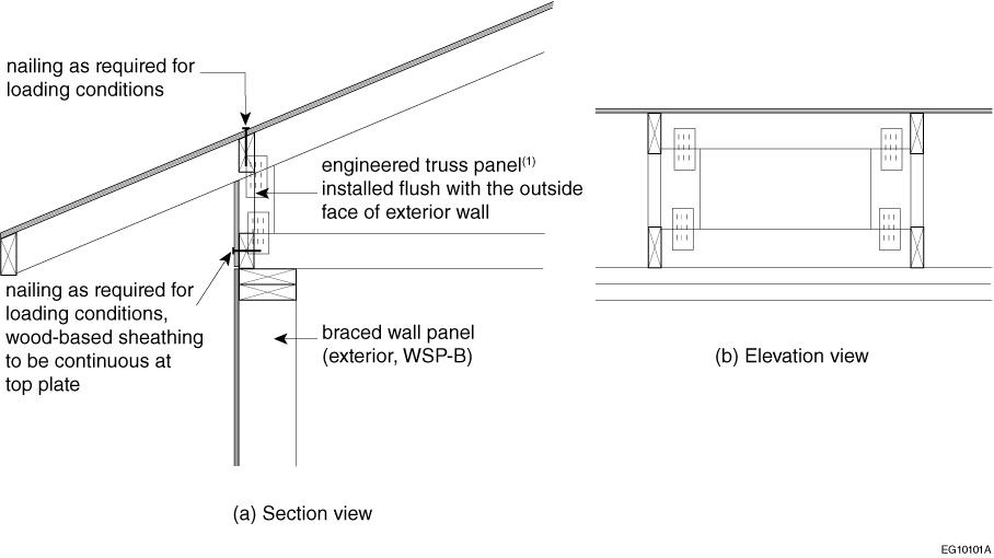
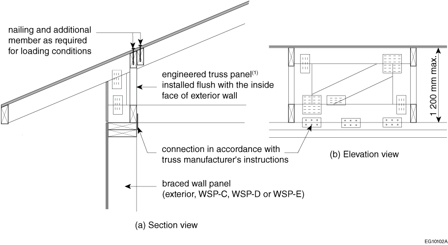
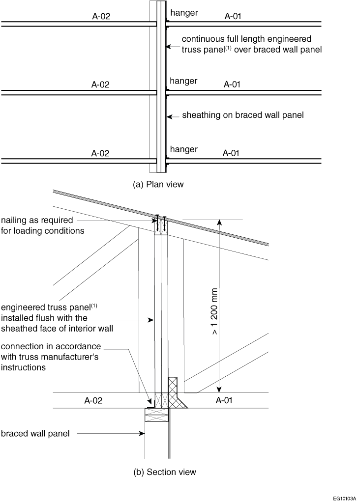
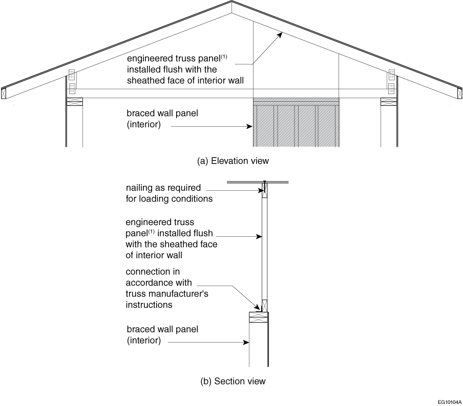
The engineered truss panel fastened to the top plate of the braced wall panel and the roof sheathing fastened to the engineered truss panel as specified by the truss design engineer to meet or exceed the connection capacity required for the reference framing typePROPOSED CHANGE Table Footnote(4) of the braced wall panel below.
Table [9.23.13.6.-B] Partial-Height BlockingPROPOSED CHANGE Table Footnote (1) to Connect Braced Wall Panels to Roof Framing
Forming Part of Clause 9.23.13.6.(2)(b)
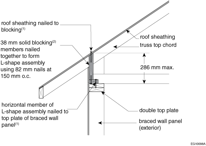
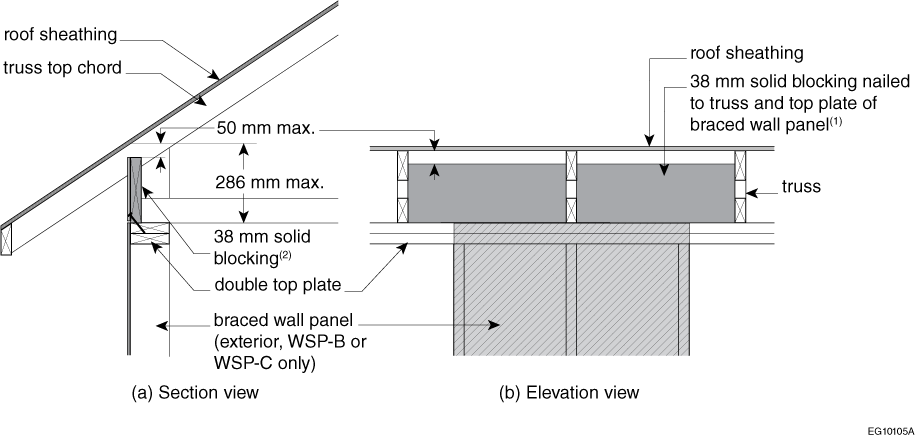
Solid blocking fastened to the top plate of the braced wall panel below using 82 mm nails at 150 mm o.c. and fastened to the roof framing with 2 per toe nailed or 3 end nailed.
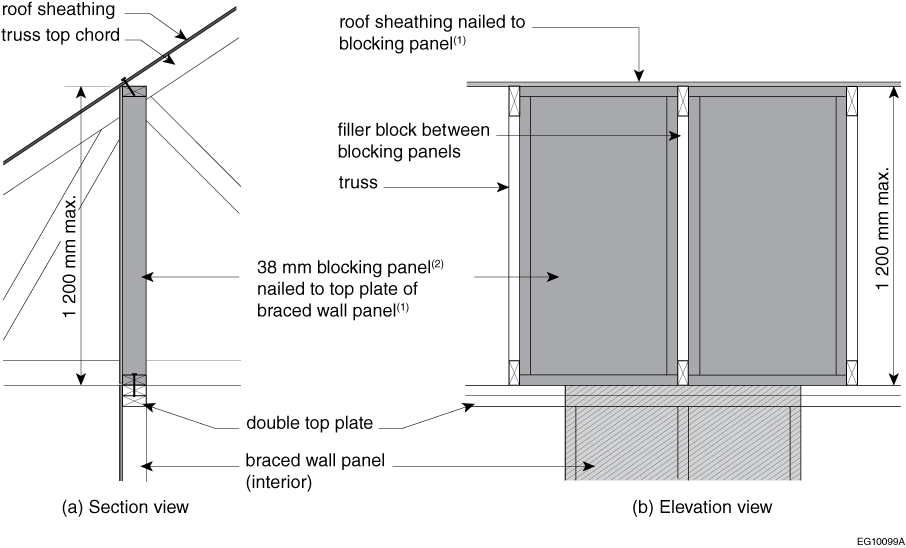
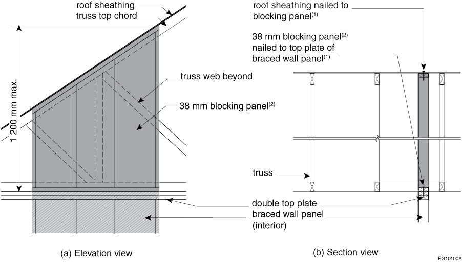
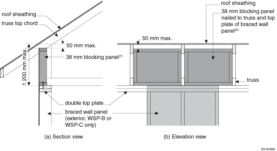
Bottom horizontal components of the blocking panel fastened to the top plate of the braced wall panel below using 82 mm nails at 150 mm o.c. and the vertical blocking components to truss web or filler blocks with 82 mm nails at 150 mm o.c.
Engineered truss panels
Designed to meet or exceed the factored shear resistance of the reference framing typePROPOSED CHANGE Table Footnote (7) of the braced wall panel below.
Specified by the truss design engineer to meet or exceed the connection capacity of the reference framing typePROPOSED CHANGE Table Footnote(6) of the braced wall panel below.
[3] --)Blocking described in Sentence (2) is not required
[a] --)where the braced wall panels described in Sentence (1) belong to
[i] --)gypsum-sheathed reference framing type GWB-A, GWB-B, GWB-C or GWB-D, or
[ii] --)wood-sheathed reference framing type WSP-A, or
[b] --)where the distance between the top of the braced wall panel and the underside of the roof sheathing is less than or equal to 140 mm.
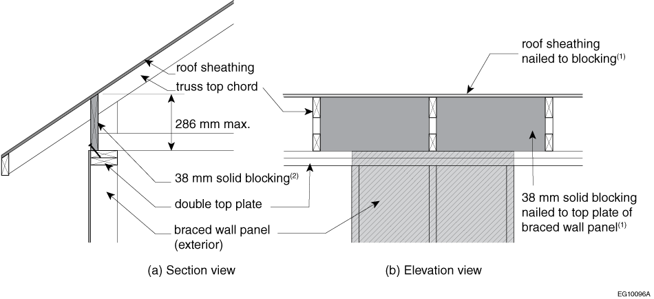
[4] --)Solid blocking is not permitted to be used where the distance between the top of the braced wall panel and underside of the roof sheathing is greater than 286 mm.
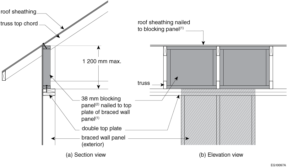
[5] --)Blocking panels are not permitted to be used where the distance between the top of the braced wall panel and underside of the roof sheathing is greater than 1 200 mm.
[6] --)Partial-height blocking is not permitted to be used where the braced wall panel below belongs to reference framing type WSP-D or WSP-E.
[7] --)Where partial-height blocking is used, the gap between the top of the blocking and the roof sheathing shall not exceed 50 mm.
[8] --)Attic or roof space venting shall comply with Subsection 9.19.1. (See Note A-9.23.13.6.(8).)
[9] --)Where the engineered truss panels referred to in Tables 9.23.13.6.-A and -B are used, these panels shall be capable of meeting or exceeding the values for factored shear resistance in Table 9.23.13.6.-C that correspond to the reference framing type of the braced wall panel below.
Table [9.23.13.6.-C] Factored Shear Resistance of the Reference Framing Type of the Braced Wall Panel
Forming Part of Sentence 9.23.13.6.(9)
Reference Framing Type
Factored Shear Resistance, kN/m
WSP-B
6.22
WSP-C
7.15
WSP-D
7.85
WSP-E
8.71
DWB
5.77
[9.23.13.7.] 9.23.13.6.Materials in Braced Wall Panels
[9.23.13.8.] 9.23.13.7.Simplified Method for Determining Minimum Length of Bracing
[9.23.13.9.] 9.23.13.8.Table Method for Determining Minimum Length of Bracing
[9.23.13.10.] 9.23.13.9.Calculation Method for Determining Minimum Length of Bracing
[9.23.13.11.] 9.23.13.10.Foundation Cripple Walls
[9.23.13.12.] 9.23.13.11.Cripple Walls in Stepped Foundations
[9.23.13.13.] 9.23.13.12.Additional System Considerations
Note A-9.23.13.5.(3) and (4)Connection of Braced Wall Panels to Roof Framing.
Braced wall panels that are sheathed with gypsum board alone have a significantly lower lateral resistance than wood-sheathed braced wall panels. For gypsum-sheathed braced wall panels, the typical lateral bracing of trusses is usually adequate to transfer the lateral loads from the bottom chords to the top chords of the truss.
The connection of interior gypsum-sheathed braced wall panels to trusses also needs to accommodate vertical movement of the roof framing in order to facilitate “truss uplift” and to prevent the gypsum board from cracking.
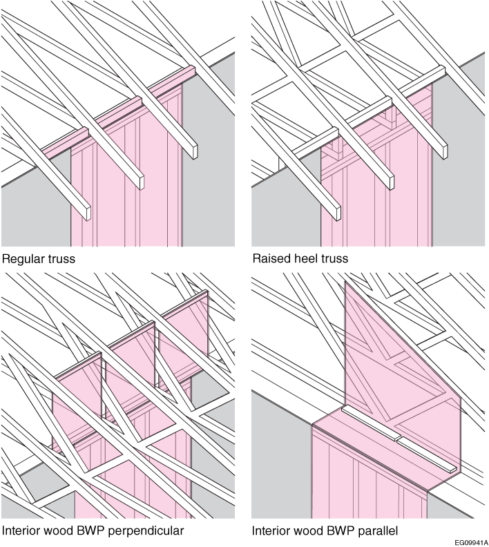
The connection of interior or exterior wood-sheathed braced wall panels (BWP), other than panels of WSP-A framing type, to roof framing is illustrated in Figure A-9.23.13.5.(3) and (4).
Figure [A-9.23.13.5.(3) and (4)] A-9.23.13.5.(3) and (4) Connection of wood-sheathed braced wall panels to roof framing (Sentence 9.23.13.5.(3))
Note A-9.23.13.6.(2)Examples of Braced Wall Panel Connections to Roof Framing.
Figure [A-9.23.13.6.(2)-A] Example of full-height solid blocking
Notes to Figure :
(1)See Table 9.23.13.6.-A for fastening details.
(2)See Table 9.23.13.6.-A for construction type.
Figure [A-9.23.13.6.(2)-B] Example of full-height solid blocking – L-shape assembly
Notes to Figure :
(1)See Table 9.23.13.6.-A for fastening details.
(2)See Table 9.23.13.6.-A for construction type.
Figure [A-9.23.13.6.(2)-C] Example of full-height blocking panels – perpendicular roof framing members and exterior braced wall panel
Notes to Figure :
(1)See Table 9.23.13.6.-A for fastening details.
(2)See Table 9.23.13.6.-A for construction type.
Figure [A-9.23.13.6.(2)-D] Example of full-height blocking panels – perpendicular roof framing members and interior braced wall panel
Notes to Figure :
(1)See Table 9.23.13.6.-A for fastening details.
(2)See Table 9.23.13.6.-A for construction type.
Figure [A-9.23.13.6.(2)-E] Example of full-height blocking panels – parallel and offset roof framing members and interior braced wall panel
Notes to Figure :
(1)See Table 9.23.13.6.-A for fastening details.
(2)See Table 9.23.13.6.-A for construction type.
Figure [A-9.23.13.6.(2)-F] Example of full-height engineered truss panels – perpendicular roof framing members and exterior braced wall panel – outside face
Note to Figure :
(1)See Table 9.23.13.6.-A.
Figure [A-9.23.13.6.(2)-G] Example of full-height engineered truss panels – perpendicular roof framing members and exterior braced wall panel – inside face
Note to Figure :
(1)See Table 9.23.13.6.-A.
Figure [A-9.23.13.6.(2)-H] Example of full-height engineered truss panels – perpendicular roof framing members and interior braced wall panel
Note to Figure :
(1)See Table 9.23.13.6.-A.
Figure [A-9.23.13.6.(2)-I] Example of full-height engineered truss panels – parallel roof framing members and interior braced wall panel
Note to Figure :
(1)See Table 9.23.13.6.-A.
Figure [A-9.23.13.6.(2)-J] Example of partial-height solid blocking – perpendicular roof framing members and exterior braced wall panel
Notes to Figure :
(1)See Table 9.23.13.6.-B for fastening details.
(2)See Table 9.23.13.6.-B for construction type.
Figure [A-9.23.13.6.(2)-K] Example of partial-height blocking panels – perpendicular roof framing members and exterior braced wall panel
Notes to Figure :
(1)See Table 9.23.13.6.-B for construction type.
(2)See Table 9.23.13.6.-B for fastening details.
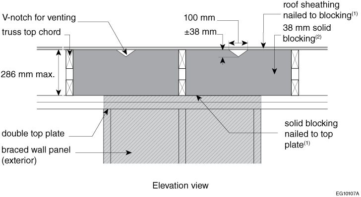
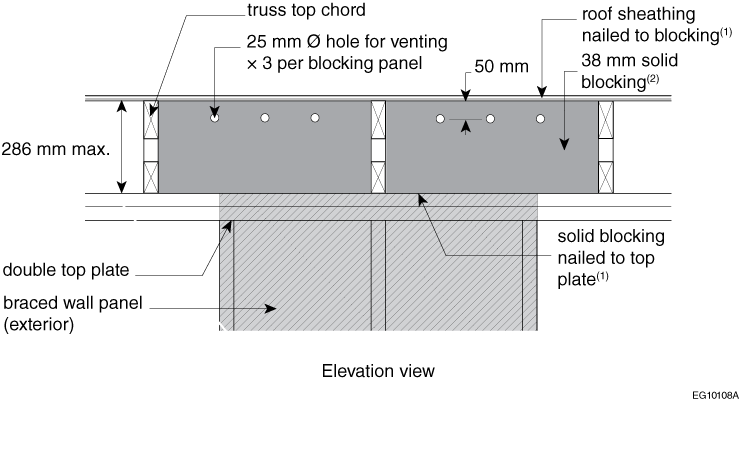
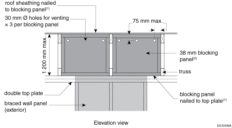
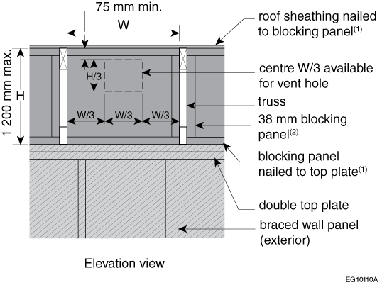
Note A-9.23.13.6.(8)Examples of Venting in Full-Height Solid Blocking and Blocking Panels with Perpendicular Roof Framing Members and Exterior Braced Wall Panels.
An unobstructed vent area at the perimeter of the attic or roof space can be maintained by notching or drilling holes through full-height solid blocking or blocking panels as shown in Figures 9.23.13.6.(8)-A to -D.
Figure [A-9.23.13.6.(8)-A] Example of venting in full-height solid blocking – notching
Notes to Figure :
(1)See Table 9.23.13.6.-B for fastening details.
(2)See Table 9.23.13.6.-B for construction type.
Figure [A-9.23.13.6.(8)-B] Example of venting in full-height solid blocking – 25 mm drilled holes
Notes to Figure :
(1)See Table 9.23.13.6.-B for fastening details.
(2)See Table 9.23.13.6.-B for construction type.
Figure [A-9.23.13.6.(8)-C] Example of venting in full-height blocking panels – 30 mm drilled holes
Notes to Figure :
(1)See Table 9.23.13.6.-B for fastening details.
(2)See Table 9.23.13.6.-B for construction type.
Figure [A-9.23.13.6.(8)-D] Example of venting in full-height blocking panels – vent hole in centre
Notes to Figure :
(1)See Table 9.23.13.6.-B for fastening details.
(2)See Table 9.23.13.6.-B for construction type.
Impact analysis
The proposed change is expected to result in cost savings. Although there are costs associated with the installation of solid blocking, blocking panels, or truss panels (see table below), the requirements, as clarified by this proposed change, provide the necessary guidance to reduce the need to pay professional fees (see the “Benefit Analysis” section below).
Cost Analysis
This proposed change does not introduce new requirements for blocking to facilitate lateral load transfer; since the requirements already exist, there is an existing cost associated with the existing requirement. However, this proposed change clarifies the requirements for blocking, which may result in cost savings.
The costs for blocking are determined based on the construction and connection details that are chosen as a result of the reasonable interpretation of the existing requirements in Sentences9.23.13.5.(3) and (4)-2025 as shown in the figures included in the explanatory Note. The cost analysis of this proposed change includes a range of costs reflecting possible interpretations of the existing requirements (and figures, i.e., the visual interpretation of the engineered solutions that are provided by a professional engineer).
The cost analysis also includes the assumptions identified below.
Table 1 shows an assessment of the difference in costs of the existing requirements for blocking compared to the requirements as clarified in this proposed change (i.e., Article9.23.13.6.-2030).
The two locations have been selected to represent both an area with low-to-moderate wind or seismic forces (i.e., Toronto, Ont.) and an area with high wind or seismic forces (i.e., Victoria, BC), using climatic data and seismic parameters from NBC TablesC-2 and C-3.
The A4building archetype features brick veneer on the front elevation and stucco siding on the sides. In Toronto, these claddings classify the construction as heavyweight. In Victoria, however, heavyweight construction would require longer exterior walls than available; therefore, vinyl siding is used instead to classify the construction as normal weight.
Table 1. Construction Costs(1)(2)(3) for Lateral Load Transfer Blocking in Two Locations
Location
Blocking Type
Sentences 9.23.13.5.(3) and (4)-2025
Article 9.23.13.6.-2030
Cost Difference
Toronto, Ont.
Solid blocking(4)(5)
$220–$320
$320
$0–$100
Blocking panels(5)(6)
$325–$680
$680
$0–$355
Engineered truss panels(7)
N/A
N/A
$41
Victoria, BC
Solid blocking(4)(5)
$310–$520
$520
$0–$210
Blocking panels(5)(6)
$425–$1005
$1005
$0–$580
Engineered truss panels(7)
N/A
N/A
$64
Notes to Table 1:
1. Costs are based on RSMeans data from Gordian for 2026 Q1.
2. Cost adjustments per RSMeans include a 15% mark-up for difficulty working within trusses, a 20% contingency allowance since the estimate is based on conceptual design, and a 10% construction management fee, plus overhead and profit.
3. The assessment of existing costs is based on Sentences9.23.13.5.(3) and (4)-2025 (as shown in the figures in the Note as specified). For the lower cost value in the third column of Table1, the analysis assumes 38×89mm blocking and 11mm OSBsheathing at the truss heel (see FiguresA-9.23.13.5.(3) and (4)-2025, Raised heel truss) with heel heights of 286mm and 600mm for solid blocking and blocking panels, respectively. For the higher cost value, the analysis assumes an engineered solution similar to that required by Article9.23.13.6.-2030. The range of existing costs associated with Sentences9.23.13.5.(3) and (4)-2025 reflects a reasonable interpretation of the figures in the explanatory Note.
4. Costs for solid blocking in accordance with Article9.23.13.6.-2030 are based on a raised heel truss between 140mm and 286mm and 38×286mm solid blocking.
5. The quantities of solid blocking and blocking panels were determined by calculating the length of required braced wall panels for the A4building archetype (see supporting documents) using the Calculation Method in NBCArticle 9.23.13.9. and are specific to the climatic data and seismic parameters for the two locations.
6. Costs for blocking panels in accordance with Article9.23.13.6.-2030 are based on a raised heel truss of 600mm and use 38×89mm top, bottom and side framing with 11mm OSBsheathing to match the WSP-B blocking panel below.
7. The cost difference for engineered truss panels is based on data provided by the Western Wood Truss Association of British Columbia and reflects expected design efficiencies resulting from the proposed clarification of the loads in Sentence9.23.13.6.(9)-2030. The resulting design efficiencies are expected to reduce costs by approximately $2.75 per 600mm tall panel between trusses and $3.10 per 1200 mm tall panel between trusses. Based on the A4building archetype, fifteen 600mm panels are required in Toronto, representing an estimated cost savings of approximately $41. In Victoria, twenty‑two 600mm panels and one 1200mm panel are required, representing an estimated cost savings of approximately $64.
Benefit Analysis
As identified in the Problem section, Subclause9.23.13.5.(3)(b)(i)-2025 lacks clarity regarding construction requirements for blocking panels, leaving the interpretation to the builder or owner. Alternatively, the roof truss manufacturer can support compliance by designing to meet the lateral load transfer requirements. In both cases, a professional engineer is likely needed to develop the solution and/or to specify the design loads, resulting in additional engineering fees. Representatives of the Western Wood Truss Association of British Columbia report that these fees are typically $1500 to $2500 in Victoria, depending on building size. The lateral load provisions in NBC2025 have not yet been adopted in Ontario; therefore, the requirement does not currently exist in Toronto and the corresponding engineering fees remain unknown. As such, professional fees in Toronto are assumed to be the same as in Victoria for the purpose of this analysis.
This proposed change benefits Code users by clarifying the requirements, which in turn means engineering fees can be saved, resulting in a cost savings of $1500 to $2500. For the purpose of this analysis, based on the area of the A4building archetype (1373ft.2), the lower end cost savings ($1500) is used for comparison against the costs provided in Table 1 above.
Conclusion
This proposed change offsets the new costs for blocking with the costs saved related to professional fees. Therefore, the cost impact for the proposed change is a net savings ranging from $920 ($1500–$580) to $1459 ($1500–$41), depending on the blocking type and location. The net cost reduction represents the overall benefit of making the proposed changes.
Enforcement implications
The proposed change provides regulators with additional prescriptive information to support the assessment of compliance, improving enforceability compared to the current NBC requirements. Multiple options are provided to allow flexibility during construction and to support enforcement across the range of scenarios that may be encountered on site.
Some training may be required, particularly in regions where lateral load bracing requirements are relatively new (e.g., areas with low-to-moderate seismic and wind loads). However, the figures included in the explanatory Note are expected to support training and improve general understanding of the requirements.
Who is affected
This proposed change addresses concerns raised by the truss industry and supports manufacturers by providing information for the design and construction of engineered truss panels where roof trusses are used as roof framing. This proposed change removes the need for roof truss manufacturers to retain professional engineers to determine the loads that engineered truss panels must be designed to meet or exceed, thereby reducing the associated time and costs.
This proposed change also provides information to support builders when site-built lateral load transfer blocking is used instead of engineered truss panels, or where the roof framing does not consist of roof trusses (e.g., where rafters or joists are used instead).
[9.23.13.1.] 9.23.13.1. ([2] 2)[F20,F22-OS1.2]Applies to assemblies required to provide fire resistance.
[9.23.13.1.] 9.23.13.1. ([2] 2)[F22-OS3.1]Applies to walls that support floors.[F22-OS3.7]Applies to walls that contain doors or windows required for emergency egress.
[9.23.13.1.] 9.23.13.1. ([2] 2)[F20,F22-OH4]Applies to walls that support floors.
[9.23.13.4.] 9.23.13.4. ([1] 1)[F20,F22-OS1.2]Applies to assemblies required to provide fire resistance.
[9.23.13.4.] 9.23.13.4. ([1] 1)[F22-OS3.1]Applies to walls that support floors.[F22-OS3.7]Applies to walls that contain doors or windows required for emergency egress.
[9.23.13.4.] 9.23.13.4. ([1] 1)[F20,F22-OH4]Applies to walls that support floors.
[9.23.13.4.] 9.23.13.4. ([1] 1)[F20,F22-OH1.1,OH1.2,OH1.3]Applies to elements that support or are part of an environmental separator.
[9.23.13.4.] 9.23.13.4. ([2] 2)[F20,F22-OS1.2]Applies to assemblies required to provide fire resistance.
[9.23.13.4.] 9.23.13.4. ([2] 2)[F22-OS3.1]Applies to walls that support floors.[F22-OS3.7]Applies to walls that contain doors or windows required for emergency egress.
[9.23.13.4.] 9.23.13.4. ([2] 2)[F20,F22-OH4]Applies to walls that support floors.
[9.23.13.4.] 9.23.13.4. ([2] 2)[F20,F22-OH1.1,OH1.2,OH1.3]Applies to elements that support or are part of an environmental separator.
[9.23.13.5.] 9.23.13.5. ([1] 1)[F20,F22-OS1.2]Applies to assemblies required to provide fire resistance.
[9.23.13.5.] 9.23.13.5. ([1] 1)[F22-OS3.1]Applies to walls that support floors.[F22-OS3.7]Applies to walls that contain doors or windows required for emergency egress.
[9.23.13.5.] 9.23.13.5. ([1] 1)[F20,F22-OH4]Applies to walls that support floors.
[9.23.13.5.] 9.23.13.5. ([1] 1)[F20,F22-OH1.1,OH1.2,OH1.3]Applies to elements that support or are part of an environmental separator.
[9.23.13.5.] 9.23.13.5. ([2] 2)[F20,F22-OS1.2]Applies to assemblies required to provide fire resistance.
[9.23.13.5.] 9.23.13.5. ([2] 2)[F22-OS3.1]Applies to walls that support floors.[F22-OS3.7]Applies to walls that contain doors or windows required for emergency egress.
[9.23.13.5.] 9.23.13.5. ([2] 2)[F20,F22-OH4]Applies to walls that support floors.
[9.23.13.5.] 9.23.13.5. ([2] 2)[F20,F22-OH1.1,OH1.2,OH1.3]Applies to elements that support or are part of an environmental separator.
[9.23.13.5.] 9.23.13.5. ([3] 3)[F20,F22-OS1.2]Applies to the assemblies required to provide fire resistance.
[9.23.13.5.] 9.23.13.5. ([3] 3)[F22-OS3.1]Applies to walls that support floors.[F22-OS3.7]Applies to walls that contain doors or windows required for emergency egress.
[9.23.13.5.] 9.23.13.5. ([3] 3)[F20,F22-OH4]Applies to walls that support floors.
[9.23.13.5.] 9.23.13.5. ([3] 3)[F20,F22-OH1.1,OH1.2,OH1.3]Applies to elements that support or are part of an environmental separator.
[9.23.13.5.] 9.23.13.5. ([4] 4)[F20,F22-OS1.2]Applies to the assemblies required to provide fire resistance.
[9.23.13.5.] 9.23.13.5. ([4] 4)[F22-OS3.1]Applies to walls that support floors.[F22-OS3.7]Applies to walls that contain doors or windows required for emergency egress.
[9.23.13.5.] 9.23.13.5. ([4] 4)[F20,F22-OH4]Applies to walls that support floors.
[9.23.13.5.] 9.23.13.5. ([4] 4)[F20,F22-OH1.1,OH1.2,OH1.3]Applies to elements that support or are part of an environmental separator.
[9.23.13.6.] -- ([1] --)[F20,F22-OS1.2]Applies to the assemblies required to provide fire resistance.
[9.23.13.6.] -- ([1] --)[F22-OS3.1]Applies to walls that support floors.[F22-OS3.7]Applies to walls that contain doors or windows required for emergency egress.
[9.23.13.6.] -- ([1] --)[F20,F22-OH4]Applies to walls that support floors.
[9.23.13.6.] -- ([1] --)[F20,F22-OH1.1,OH1.2,OH1.3]Applies to elements that support or are part of an environmental separator.
[9.23.13.6.] -- ([2] --)[F20,F22-OS1.2]Applies to the assemblies required to provide fire resistance.
[9.23.13.6.] -- ([2] --)[F22-OS3.1]Applies to walls that support floors.[F22-OS3.7]Applies to walls that contain doors or windows required for emergency egress.
[9.23.13.6.] -- ([2] --)[F20,F22-OH4]Applies to walls that support floors.
[9.23.13.6.] -- ([2] --)[F20,F22-OH1.1,OH1.2,OH1.3]Applies to elements that support or are part of an environmental separator.
[9.23.13.6.] -- ([7] --)[F20,F22-OS1.2]Applies to the assemblies required to provide fire resistance.
[9.23.13.6.] -- ([7] --)[F22-OS3.1]Applies to walls that support floors.[F22-OS3.7]Applies to walls that contain doors or windows required for emergency egress.
[9.23.13.6.] -- ([7] --)[F20,F22-OH4]Applies to walls that support floors.
[9.23.13.6.] -- ([7] --)[F20,F22-OH1.1,OH1.2,OH1.3]Applies to elements that support or are part of an environmental separator.
[9.23.13.6.] -- ([9] --)[F20,F22-OS1.2]Applies to the assemblies required to provide fire resistance.
[9.23.13.6.] -- ([9] --)[F22-OS3.1]Applies to walls that support floors.[F22-OS3.7]Applies to walls that contain doors or windows required for emergency egress.
[9.23.13.6.] -- ([9] --)[F20,F22-OH4]Applies to walls that support floors.
[9.23.13.6.] -- ([9] --)[F20,F22-OH1.1,OH1.2,OH1.3]Applies to elements that support or are part of an environmental separator.
[9.23.13.7.] 9.23.13.6. ([1] 1)[F20,F22-OS1.2]Applies to assemblies required to provide fire resistance.
[9.23.13.7.] 9.23.13.6. ([1] 1)[F22-OS3.1]Applies to walls that support floors.[F22-OS3.7]Applies to walls that contain doors or windows required for emergency egress.
[9.23.13.7.] 9.23.13.6. ([1] 1)[F20,F22-OH4]Applies to walls that support floors.
[9.23.13.7.] 9.23.13.6. ([1] 1)[F20,F22-OH1.1,OH1.2,OH1.3]Applies to elements that support or are part of an environmental separator.
[9.23.13.7.] 9.23.13.6. ([2] 2)[F20,F22-OS1.2]Applies to assemblies required to provide fire resistance.
[9.23.13.7.] 9.23.13.6. ([2] 2)[F22-OS3.1]Applies to walls that support floors.[F22-OS3.7]Applies to walls that contain doors or windows required for emergency egress.
[9.23.13.7.] 9.23.13.6. ([2] 2)[F20,F22-OH4]Applies to walls that support floors.
[9.23.13.7.] 9.23.13.6. ([2] 2)[F20,F22-OH1.1,OH1.2,OH1.3]Applies to elements that support or are part of an environmental separator.
[9.23.13.7.] 9.23.13.6. ([3] 3)[F20,F22-OS1.2]Applies to assemblies required to provide fire resistance.
[9.23.13.7.] 9.23.13.6. ([3] 3)[F22-OS3.1]Applies to walls that support floors.[F22-OS3.7]Applies to walls that contain doors or windows required for emergency egress.
[9.23.13.7.] 9.23.13.6. ([3] 3)[F20,F22-OH4]Applies to walls that support floors.
[9.23.13.7.] 9.23.13.6. ([3] 3)[F20,F22-OH1.1,OH1.2,OH1.3]Applies to elements that support or are part of an environmental separator.
[9.23.13.9.] 9.23.13.8. ([2] 2)[F20,F22-OS1.2]Applies to assemblies required to provide fire resistance.
[9.23.13.9.] 9.23.13.8. ([2] 2)[F22-OS3.1]Applies to walls that support floors.[F22-OS3.7]Applies to walls that contain doors or windows required for emergency egress.
[9.23.13.9.] 9.23.13.8. ([2] 2)[F20,F22-OH4]Applies to walls that support floors.
[9.23.13.9.] 9.23.13.8. ([2] 2)[F20,F22-OH1.1,OH1.2,OH1.3]Applies to elements that support or are part of an environmental separator.
[9.23.13.9.] 9.23.13.8. ([3] 3)[F20,F22-OS1.2]Applies to assemblies required to provide fire resistance.
[9.23.13.9.] 9.23.13.8. ([3] 3)[F22-OS3.1]Applies to walls that support floors.[F22-OS3.7]Applies to walls that contain doors or windows required for emergency egress.
[9.23.13.9.] 9.23.13.8. ([3] 3)[F20,F22-OH4]Applies to walls that support floors.
[9.23.13.9.] 9.23.13.8. ([3] 3)[F20,F22-OH1.1,OH1.2,OH1.3]Applies to elements that support or are part of an environmental separator.
[9.23.13.9.] 9.23.13.8. ([5] 5)[F20,F22-OS1.2]Applies to assemblies required to provide fire resistance.
[9.23.13.9.] 9.23.13.8. ([5] 5)[F22-OS3.1]Applies to walls that support floors.[F22-OS3.7]Applies to walls that contain doors or windows required for emergency egress.
[9.23.13.9.] 9.23.13.8. ([5] 5)[F20,F22-OH4]Applies to walls that support floors.
[9.23.13.9.] 9.23.13.8. ([5] 5)[F20,F22-OH1.1,OH1.2,OH1.3]Applies to elements that support or are part of an environmental separator.
[9.23.13.10.] 9.23.13.9. ([1] 1)[F20,F22-OS1.2]Applies to assemblies required to provide fire resistance.
[9.23.13.10.] 9.23.13.9. ([1] 1)[F22-OS3.1]Applies to walls that support floors.[F22-OS3.7]Applies to walls that contain doors or windows required for emergency egress.
[9.23.13.10.] 9.23.13.9. ([1] 1)[F20,F22-OH4]Applies to walls that support floors.
[9.23.13.10.] 9.23.13.9. ([1] 1)[F20,F22-OH1.1,OH1.2,OH1.3]Applies to elements that support or are part of an environmental separator.
[9.23.13.10.] 9.23.13.9. ([2] 2)[F20,F22-OS1.2]Applies to assemblies required to provide fire resistance.
[9.23.13.10.] 9.23.13.9. ([2] 2)[F22-OS3.1]Applies to walls that support floors.[F22-OS3.7]Applies to walls that contain doors or windows required for emergency egress.
[9.23.13.10.] 9.23.13.9. ([2] 2)[F20,F22-OH4]Applies to walls that support floors.
[9.23.13.10.] 9.23.13.9. ([2] 2)[F20,F22-OH1.1,OH1.2,OH1.3]Applies to elements that support or are part of an environmental separator.
[9.23.13.10.] 9.23.13.9. ([3] 3)[F20,F22-OS1.2]Applies to assemblies required to provide fire resistance.
[9.23.13.10.] 9.23.13.9. ([3] 3)[F22-OS3.1]Applies to walls that support floors.[F22-OS3.7]Applies to walls that contain doors or windows required for emergency egress.
[9.23.13.10.] 9.23.13.9. ([3] 3)[F20,F22-OH4]Applies to walls that support floors.
[9.23.13.10.] 9.23.13.9. ([3] 3)[F20,F22-OH1.1,OH1.2,OH1.3]Applies to elements that support or are part of an environmental separator.
[9.23.13.10.] 9.23.13.9. ([4] 4)[F20,F22-OS1.2]Applies to assemblies required to provide fire resistance.
[9.23.13.10.] 9.23.13.9. ([4] 4)[F22-OS3.1]Applies to walls that support floors.[F22-OS3.7]Applies to walls that contain doors or windows required for emergency egress.
[9.23.13.10.] 9.23.13.9. ([4] 4)[F20,F22-OH4]Applies to walls that support floors.
[9.23.13.10.] 9.23.13.9. ([4] 4)[F20,F22-OH1.1,OH1.2,OH1.3]Applies to elements that support or are part of an environmental separator.
[9.23.13.10.] 9.23.13.9. ([5] 5)[F20,F22-OS1.2]Applies to assemblies required to provide fire resistance.
[9.23.13.10.] 9.23.13.9. ([5] 5)[F22-OS3.1]Applies to walls that support floors.[F22-OS3.7]Applies to walls that contain doors or windows required for emergency egress.
[9.23.13.10.] 9.23.13.9. ([5] 5)[F20,F22-OH4]Applies to walls that support floors.
[9.23.13.10.] 9.23.13.9. ([5] 5)[F20,F22-OH1.1,OH1.2,OH1.3]Applies to elements that support or are part of an environmental separator.
[9.23.13.11.] 9.23.13.10. ([1] 1)[F20,F22-OS1.2]Applies to assemblies required to provide fire resistance.
[9.23.13.11.] 9.23.13.10. ([1] 1)[F22-OS3.1]Applies to walls that support floors.[F22-OS3.7]Applies to walls that contain doors or windows required for emergency egress.
[9.23.13.11.] 9.23.13.10. ([1] 1)[F20,F22-OH4]Applies to walls that support floors.
[9.23.13.11.] 9.23.13.10. ([1] 1)[F20,F22-OH1.1,OH1.2,OH1.3]Applies to elements that support or are part of an environmental separator.
[9.23.13.11.] 9.23.13.10. ([2] 2)[F20,F22-OS1.2]Applies to assemblies required to provide fire resistance.
[9.23.13.11.] 9.23.13.10. ([2] 2)[F22-OS3.1]Applies to walls that support floors.[F22-OS3.7]Applies to walls that contain doors or windows required for emergency egress.
[9.23.13.11.] 9.23.13.10. ([2] 2)[F20,F22-OH4]Applies to walls that support floors.
[9.23.13.11.] 9.23.13.10. ([2] 2)[F20,F22-OH1.1,OH1.2,OH1.3]Applies to elements that support or are part of an environmental separator.
[9.23.13.11.] 9.23.13.10. ([3] 3)[F20,F22-OS1.2]Applies to assemblies required to provide fire resistance.
[9.23.13.11.] 9.23.13.10. ([3] 3)[F22-OS3.1]Applies to walls that support floors.[F22-OS3.7]Applies to walls that contain doors or windows required for emergency egress.
[9.23.13.11.] 9.23.13.10. ([3] 3)[F20,F22-OH4]Applies to walls that support floors.
[9.23.13.11.] 9.23.13.10. ([3] 3)[F20,F22-OH1.1,OH1.2,OH1.3]Applies to elements that support or are part of an environmental separator.
[9.23.13.11.] 9.23.13.10. ([4] 4)[F20,F22-OS1.2]Applies to assemblies required to provide fire resistance.
[9.23.13.11.] 9.23.13.10. ([4] 4)[F22-OS3.1]Applies to walls that support floors.[F22-OS3.7]Applies to walls that contain doors or windows required for emergency egress.
[9.23.13.11.] 9.23.13.10. ([4] 4)[F20,F22-OH4]Applies to walls that support floors.
[9.23.13.11.] 9.23.13.10. ([4] 4)[F20,F22-OH1.1,OH1.2,OH1.3]Applies to elements that support or are part of an environmental separator.
[9.23.13.12.] 9.23.13.11. ([1] 1)[F20,F22-OS1.2]Applies to assemblies required to provide fire resistance.
[9.23.13.12.] 9.23.13.11. ([1] 1)[F22-OS3.1]Applies to walls that support floors.[F22-OS3.7]Applies to walls that contain doors or windows required for emergency egress.
[9.23.13.12.] 9.23.13.11. ([1] 1)[F20,F22-OH4]Applies to walls that support floors.
[9.23.13.12.] 9.23.13.11. ([1] 1)[F20,F22-OH1.1,OH1.2,OH1.3]Applies to elements that support or are part of an environmental separator.