Removing ACH50 and Harmonizing Airtightness Requirements in Section 9.36.
Description:
This proposed change replaces ACH50 with NLR50 as the regulating airtightness metric in Section 9.36. and revises the airtightness requirements in the compliance paths and for proposed house modeling.
Related Proposed Change(s):
PCF 1954
Problem
Section 9.36. of Division B of the National Building Code of Canada (NBC) currently uses ACH50 (air changes per hour at 50Pa pressure differential) for energy modeling of the proposed and reference houses. Given that ACH50 is a measurement of airtightness that expresses air flow as a function of the air volume within a building, a fixed ACH50 value for the reference house (Sentence9.36.5.14.(2)) or proposed house (Sentence9.36.5.10.(9)) does not sufficiently account for variations in surface-area-to-volume ratios (SVs) or the geometry of buildings. This limitation creates a misalignment between the requirements of Subsection 9.25.3. and Articles9.36.2.9. and 9.36.2.10., which specifically address improvements of the building envelope assembly that are not tied to the geometry or physical size of the building.
The inclusion of multiple metrics, i.e., ACH50, NLR50 (normalized leakage rate at 50Pa pressure differential), and NLA10 (normalized leakage area at 10 Pa pressure differential), to define airtightness levels in Tables9.36.6.4.-A and 9.36.6.4.-B adds unnecessary complexity and confusion to the Code by implying equivalency between the three metrics that is only true at a specific SV.
A related issue adding yet more complexity is the lack of consistency between the airtightness values assigned to the proposed house in the performance path (Subsection9.36.5.) and in the tiered performance path (Subsection9.36.7.). Currently, the performance path permits an ACH50 value of 2.5 in the proposed house when the requirements of Subsection9.25.3. and Articles9.36.2.9 and 9.36.2.10 are met. The tiered performance path only allows an ACH50 value of 3.2 when the same requirements are met unless a blower door test is performed. There is no requirement in the tiered performance path to use the results of the blower door test. Also, no differentiation is made in either path between the use of these assumed ACH50 values in attached houses and detached houses.
To address the issues listed above, this proposed change suggests
using NLR50 as the regulating metric to align the airtightness metrics with building envelope requirements,
simplifying the airtightness metric in the Code by removing ACH50 from all airtightness level tables and only using ACH50 as a calculated value from NLR50 for energy model input, and
aligning the tiered performance path with the performance path by only referencing NLR50 values.
Justification
Using NLR50 would increase internal Code alignment by addressing air leakage through the building envelope assemblies and create a more equitable metric to measure building envelope airtightness.
1. Alignment of Airtightness Metrics with Building Envelope Requirements
NLR50 (in L/s×m2) is an airtightness metric that is based on the airtightness of assemblies and surfaces, which is in turn directly aligned with the materials used and assemblies built by the builders. The prescriptive requirements in Subsection 9.25.3. and Articles 9.36.2.9. and 9.36.2.10. of Division B of NBC address the airtightness of materials and assemblies as a means of achieving a continuous air barrier system that is a part of the building envelope. Table 1 shows the volume, surface area and ACH50 of three detached houses of varying size, all with an applied consistent NLR50 building envelope airtightness of 0.89 L/(s×m2).
Table 1. Examples of the Conversion of Airtightness Metrics for Detached Houses
Description
Volume (V)
Total Surface Area (At)
NLR50
ACH50
1300 ft.2 slab-on-grade/ground (SOG) construction
290m3
292m2
0.89L/(s×m2)
3.23
3300 ft.2 with basement
791m3
605m2
0.89L/(s×m2)
2.45
4000 ft.2 with basement
1534m3
969.7m2
0.89L/(s×m2)
2.03
Table 1 shows that houses built with the same quality of air barrier system achieve different ACH50 values due to the impact of the variation in geometry on the calculations and not because of differences in how the air barrier system was constructed.
Assumptions about airtightness in the reference house are, therefore, proposed to also vary with geometry based on a fixed NLR50 building envelope value, rather than by assuming a fixed ACH50 value as is currently prescribed by Article 9.36.5.14. The result is a definition of the reference house that applies a consistent building envelope airtightness, rather than a variable airtightness controlled by a fixed application of ACH50. It is proposed that the NLR50 values from level AL-1A in Table 9.36.6.4.-A and level AL-1B in Table 9.36.6.4.-B are more appropriate for all reference house cases depending on the type of house and the test performed, i.e.:
0.89 L/(s×m2) for detached zones, and
1.17 L/(s×m2) for attached zones.
To determine compliance with the airtightness levels in Article 9.36.6.4., unguarded test results would continue to use Table 9.36.6.4-B, while guarded test results would be compared against Table 9.36.6.4-A.
Application of NLR50 and Ae for Modelling Attached Houses
There exists at present an additional misalignment in the airtightness assumptions used in modeling attached houses. The NBC requires that attached houses use an ACH50 value of 3.0 (when unguarded testing is performed), but this value is not adjusted to address the degree of attachment of the modeled house (reference or proposed). As a result, the energy model assumes all air leakage associated with this ACH50 value to be coming from unconditioned space, thereby, effectively overestimating the percentage of heat loss attributed to air leakage for attached houses.
It is possible to overcome this error using guarded testing; however, this type of test is typically impractical and expensive for attached houses. Since unguarded testing provides the most practical and cost-effective method for airtightness testing, a work-around is required to fairly assess the acceptable airtightness of attached houses when using an energy model.
It is proposed that only the exposed area (Ae) be used when converting NLR50 to ACH50. An assumption is made that the rate of air leakage across all surfaces facing the interior of an attached unit is the same. Ae is defined as the interior surface area of exterior walls, ceilings and floors that separate conditioned from unconditioned space. A party wall, for example, would not be considered exposed area as the space on either side is conditioned, even though the conditioned areas are located in different suites.
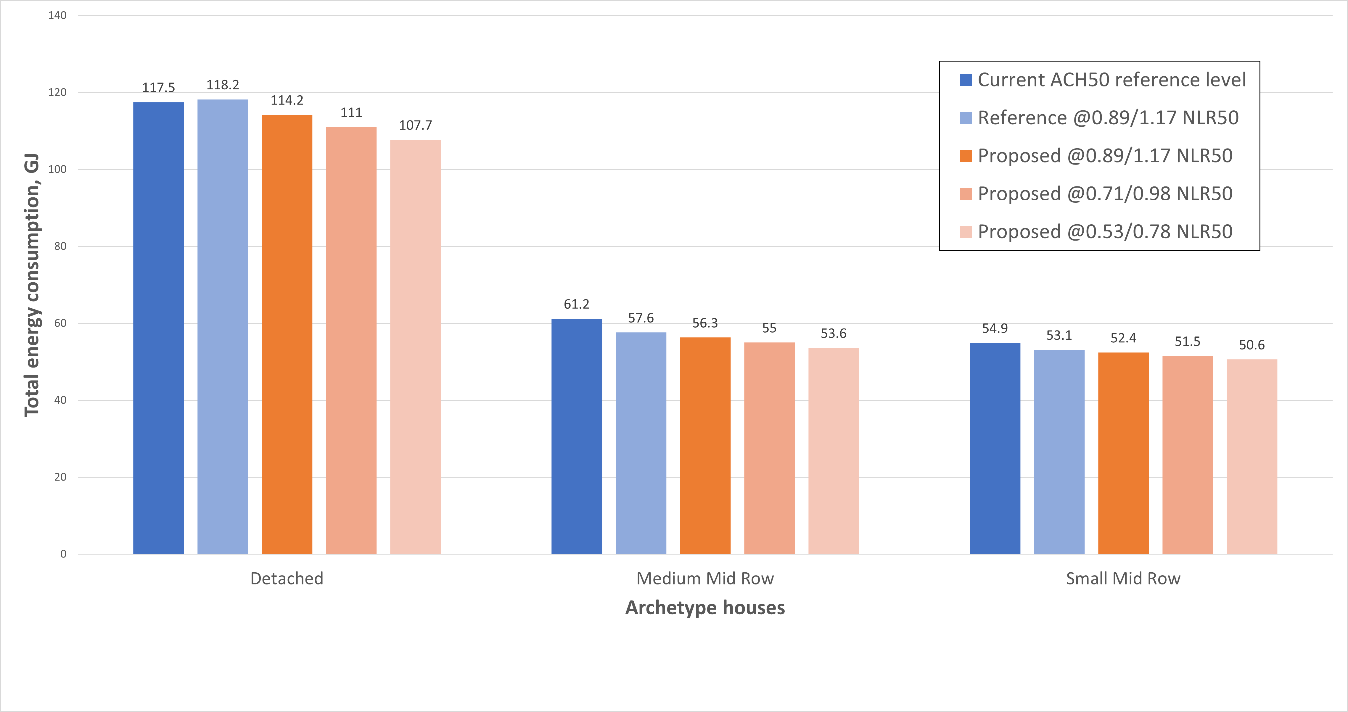
Figure 1 shows how the following three archetype houses were evaluated to determine the overall impact of this approach:
detached house, 785 m3, 0.77 SV
medium mid-row house, 402 m3, 48% attached, 0.95 SV
small mid-row house, 267 m3, 48% attached, 1.02 SV
Each archetype house was modeled five times, as follows:
Current ACH50-Based Reference House (in NBC 2020)
NLR50-Based Reference House (in this PCF; NLR50 converted to ACH50)
Proposed House Airtightness Level 1 (NLR50 converted to ACH50)
Proposed House Airtightness Level 2 (NLR50 converted to ACH50)
Proposed House Airtightness Level 3 (NLR50 converted to ACH50)
Results
Figure 1 shows the total energy consumption for each archetype house in this progression. The arrows above the bar charts (with associated ∆% values) indicate the percentage improvement directly related to improvements in airtightness for the proposed house:
Figure 1. Comparison of impact on energy consumption using different airtightness metrics as regulating metric by archetype
The results in Figure 1 demonstrate how the contribution of airtightness to energy savings appears reasonable using this approach, reflecting less impact on houses with less exposed area.
The following observations can be made:
Because the NLR50 value is converted to ACH50 using only the exposed area (Ae), the calculated ACH50 input values (for use in the model) decrease as the degree of attachment increases.
The total energy use of the reference house for attached houses is substantially reduced, while having only minimal impact overall on detached houses of average size.
In summary, using Ae in all cases provides simplicity and consistency for Code users while reducing the overestimation of heat loss due to air leakage in the current Code.
2. Simplification of Airtightness Metrics
Since most energy modeling software uses ACH50 values as an input, ACH50 should remain in Section 9.36. as a calculated value for input to energy models. However, unless the value is the measured result of a blower door test, it would always be calculated based on the NLR50 values and account for the actual geometry of the house. This situation would apply to the reference house in all cases and to the proposed house where an assumed or prescriptive airtightness value is permitted to be used. The calculation required to convert NLR50 to ACH50 is simple and only requires that both the volume and total surface area of the tested zone be known; this is typically already the case, with the exception of attached houses, where an additional small calculation may be required to determine the attached surface area. This approach would allow ACH50 to be removed from NBC Tables 9.36.6.4.-A and 9.36.6.4.-B, greatly simplifying the requirements.
3. Alignment of Performance and Tiered Performance Paths
To further improve consistency and clarity in the Code, this proposed change also revises the tiered performance path and performance path to only reference NLR50 values to reconcile the current discrepancies between the two paths.
Under the current tiered performance path (see Sentence 9.36.7.3.(9)), Code users are limited to an ACH50 value of 3.2, even if the prescriptive requirements of Subsection 9.25.3. and Articles 9.36.2.9 and 9.36.2.10. are met, unless a blower door test is performed. In the performance path (see Sentence 9.36.5.10.(9)), compliance with the same prescriptive requirements allows the use of an ACH50 value of 2.5 without a blower door test. This structure disproportionately impacts houses that have limited or costly access to blower door testing, such as those in remote locations. It is also important to note that Code users are not required to use the outputs from the blower door test where one is performed. Further, both prescribed values are fixed ACH50 values, which are subject to many of the same concerns outlined in the Justification section.
This proposed change revises both sections as follows:
both paths reference NLR50 values only,
where prescriptive compliance is demonstrated, both paths reference one NLR50 value for detached houses and a different NLR50 value for attached houses. Since this proposed change affects only prescriptive airtightness, determination based on test method (guarded or unguarded) does not apply. The values would be aligned with the airtightness levels set out in Article 9.36.6.4., and
both paths use the same criteria for compliance and application of the prescriptive airtightness value, without the requirement for blower door testing.
This proposed change would make consistent the application of prescriptive airtightness in Section 9.36. and the alignment with the proposed change to NLR50 as the governing airtightness metric in the Code.
PROPOSED CHANGE
[9.36.5.10.] 9.36.5.10.Modeling Building Envelope of Proposed House
[1] 1)Except as provided in Sentences (2)and (3), the energy model calculations for the proposed house shall be consistent with the proposed construction specifications for that house with regard to
[a] a)the area of the above-ground portion of foundation walls,
[b] b)the effective thermal resistance of above-ground walls, ceilings below attics, roof assemblies and rim joists,
[c] c)the maximum overall thermal transmittance of doors, as calculated in accordance with Sentence 9.36.2.2.(3),
[d] d)the effective thermal resistance of below-ground walls and slabs-on-ground,
[e] e)exterior walls, roof-ceiling assembly, doors, walls, exposed floors, and floors in contact with the ground,
[f] f)distribution, orientation and area of fenestration and doors, as calculated in accordance with Article 9.36.2.3.,
[g] g)solar heat gain coefficient and overall thermal transmittance of fenestration, as calculated in accordance with Sentence 9.36.2.2.(3),
[h] h)configuration of insulation in assemblies in contact with the ground, and
[i] i)effective thermal resistance of foundation walls.
[2] 2)Except for penetrations, slab-on-ground edge insulation and assemblies with embedded heating pipes, where a building envelope component or assembly covers less than 2% of the total area of the assembly type to which it belongs, its thermal characteristics are not required to be calculated as belonging to a distinct assembly, provided the area of the component or assembly is included in an adjacent assembly having the same orientation (See Note A-9.36.5.10.(2)PROPOSED CHANGE A-9.36.5.10.(2).)
[3] 3)Building envelope assemblies with the same thermal characteristics and orientation are not required to be calculated as distinct assemblies, provided their area is included in an adjacent assembly.
[4] 4)Building envelope assemblies and components separating conditioned space from enclosed unconditioned space shall have a solar heat gain coefficient equal to 0.
[5] 5)Except as stated in Sentence 9.36.5.6.(9), the energy model calculations for the proposed house shall account for the effects of exterior permanent and fixed shading devices, including fins, overhangs, and light shelves, on solar heat gain.
[6] 6)Where thermal mass is included in the energy model calculations for the proposed house, it shall be set as
[a] a)the specified mass up to the inside edge of insulation in exterior walls, the mass of interior walls, the mass up to the centre-line of party walls, and the mass of floors, as applicable,
[b] b)the specified mass of the building envelope assembly, where the energy model calculations include a transient analysis of thermal transfer of the entire building envelope assembly, or
[c] c)a default value of 0.060 MJ/(m2×°C).
[7] 7)Exterior walls, roofs and exposed floors shall have a solar absorptance of 0.4.
[8] 8)The orientation of the foundation of the proposed house as constructed shall be within 22.5° of the orientation used in the energy model calculations.
[9] 9)The airtightness used in the energy model calculations for the proposed house shall be
[a] a)where the construction complies with Section 9.25.,3.2 air changes per hour1.25 L/(s×m2) at 50 Pa pressure differential with a pressure exponent of 0.67, where the construction complies with Section 9.25.,
[b] b)2.5 air changes per hourat 50 Pa pressure differential with a pressure exponent of 0.67, where it can be shown that the air barrier system is constructed in accordance with Subsection 9.25.3. and Articles 9.36.2.9.and 9.36.2.10., or
[i] --)1.17 (L/s×m2) at 50 Pa pressure differential with a pressure exponent of 0.67 for attached zones, and
[ii] --)0.89 (L/s×m2) at 50 Pa pressure differential with a pressure exponent of 0.67 otherwise, or
[c] c)the airtightness determined in accordance with Sentence 9.36.6.3.(1) expressed as
[i] i)the number of air changes per hournormalized leakage rate at 50 Pa pressure differential with a pressure exponent determined through a multi-point test, and
[ii] ii)the calculated equivalent leakage area at 50 Pa pressure differential.
(See Note A-9.36.5.10.(9) and (10).)
[10] 10)For compliance with Clause (9)(c),
[a] --)a design airtightness valuenormalized leakage rate at 50 Pa pressure differential with a pressure exponent of 0.67 shall be assigned for use in the energy model until the actual airtightness is measured.,and
[b] --)where the proposed house contains attached zones and their airtightness is determined using the unguarded method, only the exposed area of the tested zone shall be used for
[i] --)conversion between normalized leakage rate at 50 Pa pressure differential and air changes per hour at 50 Pa pressure differential, and
[ii] --)determination of the equivalent leakage area at 50 Pa pressure differential.
(See Note A-9.36.5.10.(9) and (10).)
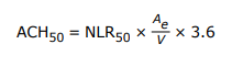
Note A-9.36.5.10.(9) and (10)Conversion of NLR50 to ACH50 for Use in the Energy Model.
The normalized leakage rate, also known as the normalized airflow rate, is defined as the airflow rate divided by the surface area of the tested zone. Unless otherwise specified, the surface area should include the total building envelope area of the tested zone, including below-grade areas and areas attached to conditioned space. The normalized leakage rate at 50 Pa pressure differential (NLR50) is calculated in accordance with CAN/CGSB 149.10, “Determination of the airtightness of building envelopes by the fan depressurization method.”
To convert NLR50 to air changes per hour at 50 Pa pressure differential (ACH50) for use in the energy model, the following formula can be used:
where
ACH50
= air changes per hour at 50 Pa pressure differential,
NLR50
= normalized leakage rate at 50 Pa pressure differential, in L/(s×m2),
Ae
= exposed area of tested zone, measured at the interior surfaces of exterior walls, ceilings and floors, in m2, and
V
= volume of the tested zone, measured at the interior surfaces of walls, ceilings and floors, in m3.
Where the unguarded method is used to test an attached zone, the NLR50 value should be calculated using the total surface area of the tested zone before determining the ACH50 value or the equivalent leakage area at 50 Pa pressure differential (ELA50) for use in the energy model.
[9.36.5.14.] 9.36.5.14.Modeling Building Envelope of Reference House
[1] 1)The energy model calculations for the reference house shall include the same values as those used for the proposed house with regard to
[a] a)the gross area of above-ground portion of foundation walls,
[b] b)soil conditions,
[c] c)the orientation of the foundation, and
[d] d)the ratio of fenestration area to opaque area of doors.
[2] 2)The energy model calculations for the reference house shall use the following values:
[a] a)0.060 MJ/(m2×°C) for thermal mass,
[b] b)a solar absorptance of 0.4 for the exterior walls, roofs and exposed floors,
[c] c)0.26 for the solar heat gain coefficient of fenestration,
[d] d)an airtightness of
[i] i)3.0 air changes per hour1.17 L/(s×m2) at 50 Pa pressure differential for attached zones, where the airtightness used for the proposed house is determined in accordance with Sentence 9.36.6.3.(1) using the unguarded method, and
[ii] ii)2.5 air changes per hour0.89 L/(s×m2) at 50 Pa pressure differential otherwise, and
[e] e)a pressure exponent equal to
[i] --)the pressure exponent used for the proposed house where this value is less than 0.67, and
[ii] --)0.67 otherwise, 0.67.
(See Note A-9.36.5.10.(9) and (10).)
[3] --)For conversion between the normalized leakage rate at 50 Pa pressure differential set out in Subclause (2)(d)(i) and air changes per hour at 50 Pa pressure differential, only the exposed area of the tested zone shall be used.
[4] 3)The effective thermal resistance and overall thermal transmittance values, as applicable, used in the energy model calculations for the reference house shall be determined for the applicable heating degree-day zone in accordance with
[a] a)Table 9.36.2.6.-A for walls, ceilings below attics, roof assemblies and rim joists,
[b] b)Table 9.36.2.7.-A for doors, and
[c] c)Table 9.36.2.8.-A for below-grade walls and slabs-on-ground.
[5] 4)Except as provided in Sentences (5)and (6), the exterior walls, roof-ceiling assembly, doors, walls, exposed floors, and floors of the reference house that are in contact with the ground shall have the same area as those of the proposed house.
[6] 5)The area and orientation of fenestration and doors of the reference house shall be modeled as being equally distributed on all sides of the house.
[7] 6)The gross wall area and the area of fenestration and doors of the reference house shall be determined in accordance with Article 9.36.2.3.
[8] 7)Windows and other glazed components in the reference house shall have a maximum overall thermal transmittance as required in Table 9.36.2.7.-A for the applicable heating degree-day category.
[9] 8)The configuration of insulation in assemblies of the reference house that are in contact with the ground shall be modeled as conforming to Article 9.36.2.8.
[10] 9)Foundation walls shall be modeled using the applicable effective thermal resistance values in Table 9.36.2.8.-A and as conforming to Sentence 9.36.2.8.(2).
[11] 10)The fenestration and door area to gross wall area ratio (FDWR) of the reference house shall be
[a] a)for houses containing one or two dwelling units,
[i] i)as per the proposed house, where its FDWR is between 17% and 22%,
[ii] ii)17%, where the FDWR of the proposed house is less than 17%, or
[iii] iii)22%, where the FDWR of the proposed house is greater than 22%, and
[b] b)for buildings of residential occupancy containing more than two dwelling units,
[i] i)the FDWR determined in Clause (a) for the areas determined in accordance with Sentence 9.36.2.3.(2) and, where the FDWR determined in accordance with the calculation in Sentence 9.36.2.3.(3) only does not exceed 40%, or
[ii] ii)40% of the gross wall area enclosing conditioned space where the area of fenestration and doors is greater than 40% of the gross wall area enclosing conditioned space determined in accordance with Sentence 9.36.2.3.(2).
(See Note A-9.36.5.14.(10)PROPOSED CHANGE A-9.36.5.14.(10).)
[9.36.6.4.] 9.36.6.4.Determination of Airtightness Level
[1] 1)Compliance with an Airtightness Level listed in Table 9.36.6.4.-Aor 9.36.6.4.-B shall be determined in accordance with this Article using the value of ACH50, NLA10, or NLR50 determined in accordance with Sentence 9.36.6.3.(2).
[2] 2)For the purposes of Sentence (3)and (4), the Airtightness Level for buildings or dwelling units containing more than one zone shall be the lowest Airtightness Level achieved for the zones therein. (See Note A-9.36.6.4.(2)PROPOSED CHANGE A-9.36.6.4.(2).)
[3] 3)Except as provided in Sentence (4), the Airtightness Level for single zones and attached zones shall be determined by complying with one of the corresponding airtightness values stipulated in Table 9.36.6.4.-A.
Table [9.36.6.4.-A] 9.36.6.4.-A Airtightness Levels for Single Zones and Attached Zones Determined Using the Guarded Method Forming Part of Sentences 9.36.6.3.(2), [9.36.6.4.] 9.36.6.4.([1] 1)and ([3] 3), and 9.36.8.8.(1)
Airtightness Levels
Airtightness Metrics
ACH50
NLA10, cm2/m2
NLR50, L/(s×m2)
Maximum Airtightness Values
AL-1A
2.5
1.20
0.89
AL-2A
2.0
0.96
0.71
AL-3A
1.5
0.72
0.53
AL-4A
1.0
0.48
0.35
AL-5A
0.6
0.29
0.21
[4] 4)Where the unguarded method is used to determine the airtightness of an attached zone, the Airtightness Level shall be determined by complying with one of the corresponding airtightness values stipulated in Table 9.36.6.4.-B, provided the zone is tested independently.
Table [9.36.6.4.-B] 9.36.6.4.-B Airtightness Levels for Attached Zones Determined Using the Unguarded Method Forming Part of Sentences 9.36.6.3.(2), [9.36.6.4.] 9.36.6.4.([1] 1)and ([4] 4), and 9.36.8.8.(1)
Airtightness Levels
Airtightness Metrics
ACH50
NLA10, cm2/m2
NLR50, L/(s×m2)
Maximum Airtightness Values
AL-1B
3.0
1.92
1.17
AL-2B
2.5
1.6
0.98
AL-3B
2.0
1.28
0.78
AL-4B
1.5
0.96
0.59
AL-5B
1.0
0.64
0.39
AL-6B
0.6
0.38
0.23
Note A-9.36.6.4.(2)Determining Airtightness Level of Buildings with Multiple Zones Having Different Airtightness Levels.
The lowest Airtightness Level determined for any zone in a building or dwelling unit with multiple zones is used to determine compliance with the tiered energy performance requirements. For example, in a building with two zones, if one zone achieves Airtightness Level AL-2A/2B through the NLR50 metric, while the other zone achieves Airtightness Level AL-3A/3B through the ACH50 metric, the Airtightness Level for the building as a whole would be AL-2A/2B.
[1] 1)Except where otherwise stated in this Article, the proposed and reference houses shall be modeled in accordance with Subsection 9.36.5. to determine
[a] a)the annual energy consumption of the proposed house and the house energy target of the reference house,
[b] b)the annual gross space heat loss of the proposed and reference houses calculated in accordance with Sentence (5), and
[c] c)the peak cooling load of the proposed and reference houses (see Sentence (4)).
(See Note A-9.36.7.3.(1)PROPOSED CHANGE A-9.36.7.3.(1).)
[2] 2)The peak cooling load for the proposed house shall not be greater than the peak cooling load for the reference house. (See Sentence (4).)
[3] 3)Except for energy performance tier 1, where space heating is provided by a heat pump in the proposed house, the reference house shall be modeled using
[a] a)equipment of the same type as the secondary or back-up system in the proposed house, but made to comply with the energy efficiency requirements of Article 9.36.3.10., or
[b] b)electric resistance heaters, where no back-up is provided in the proposed house.
[4] 4)Where cooling systems are not installed in the proposed house, both the proposed and reference houses shall have additional models using appropriately sized space-cooling equipment serving all conditioned spaces to determine the peak cooling load. (See Note A-9.36.7.3.(4)PROPOSED CHANGE A-9.36.7.3.(4).)
[5] 5)The annual gross space heat loss shall be calculated as the sum of the cumulative heat loss from
[a] a)conduction across opaque and transparent elements of the building envelope,
[b] b)air infiltration and exfiltration, and
[c] c)mechanical ventilation.
(See Note A-9.36.7.3.(5)PROPOSED CHANGE A-9.36.7.3.(5).)
[6] 6)The percent heat loss reduction shall be calculated by subtracting the annual gross space heat loss of the proposed house from the annual gross space heat loss of the reference house and dividing the result by the annual gross space heat loss of the reference house.
[7] 7)The percent improvement shall be calculated by subtracting the annual energy consumption of the proposed house from the house energy target of the reference house and dividing the result by the house energy target of the reference house.
[8] 8)The percent house energy target shall be calculated by dividing the annual energy consumption of the proposed house by the house energy target of the reference house.
[9] 9)The airtightness value used in the energy model calculations for the proposed house shall be the airtightness value set out in Sentence 9.36.5.10.(9).
[a] a)the airtightness value set out in Clause 9.36.5.10.(9)(a), or
[b] b)where an airtightness test is to be conducted, a design airtightness, until the airtightness has been measured in accordance with Sentence 9.36.6.3.(1)and the appropriate airtightness value set out in Sentence 9.36.5.10.(9) can be selected.
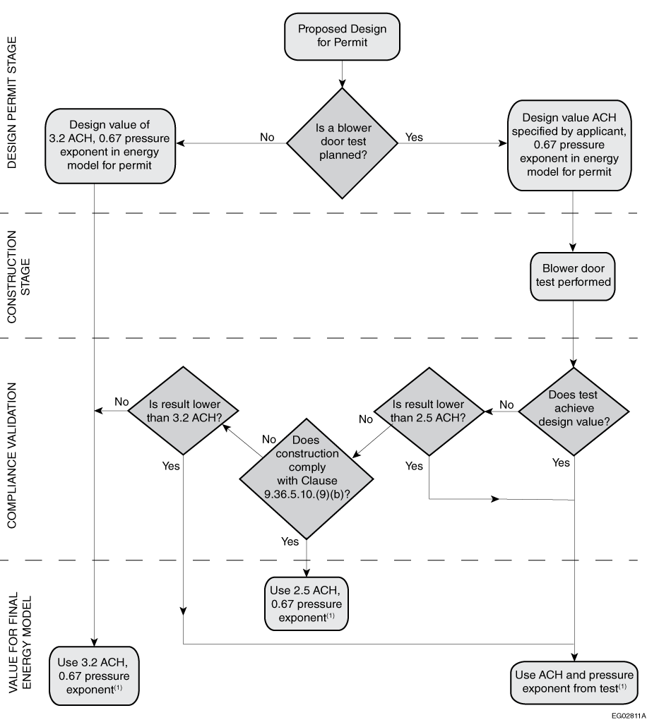
The flow chart in Figure A-9.36.7.3.(9) outlines the intended interpretation of Sentence 9.36.7.3.(9). Airtightness testing is voluntary.,however, not testing will result in the proposed house model using a default airtightness of 3.2 air changes per hour (ACH)at 50 Pa pressure difference and a pressure exponent of 0.67If performed, airtightness testing provides the option of using the result instead of the prescribed airtightness value in the modeling of the proposed house. Testing the airtightness of a building will lead to more certainty regarding the building's energy performance, which is more important for compliance with higher-tier targets.
Figure [A-9.36.7.3.(9)] A-9.36.7.3.(9) Determining the appropriate airtightness value to use in the energy model calculations in the tiered energy performance compliance path
Note to Figure A-9.36.7.3.(9):
(1)Airtightness value and pressure exponent of reference house shall be as per Sentence 9.36.5.14.(2).
Where testing is to be carried out, Code users may use a design value for ACHthe normalized leakage rate at 50 Pa pressure differentialce(NLR50) in the proposed house that they expect to achieve upon testing. Good airtightness is a significant contributor to energy-efficient performance and is likely to be needed to achieve the higher energy performance tiers;, however, it requires careful detailing and planning. Caution is advised when choosing a design airtightness value, especially for Code users who are not used to delivering highly airtight buildings. Industry resources are available to assist with selecting and achieving a design airtightness.
Once an airtightness test has been performed, Code users may choose whether to use the test result, the default NLR50 value of 3.2ACH at 50 Pa pressure difference1.25 L/(s×m2) or, where the requirements of Clause 9.36.5.10.(9)(b) have been met, 2.5 ACH at 50 Pa pressure difference. It is important to note that a tested pressure exponent may only be used in cases where the tested ACH is used, anNLR50 value of 0.89 L/(s×m2) for single zones or 1.17 L/(s×m2) for attached zones.
The airtightness value and pressure exponent to be used in the modeling of the reference house are determined in accordance with Sentence 9.36.5.14.(2).
Impact analysis
Impact on Energy Modeling
Updates to energy modeling software that allow NLR50 values to be input directly may prove convenient for Code users, but are not a barrier to this proposed change. Energy models will still be able to use ACH50 values: either measured directly by blower door test or by conversion from NLR50 using the following formula, as proposed in explanatory NoteA-9.36.5.10.(9)(c)(i):
Because the conversion between ACH50 and NLR50 requires only the exposed area (Ae) and volume (V) (both known quantities when performing a blower door test or energy modeling), there would be no additional cost of implementation to builders for this proposed change.
Application of a calculated ACH50 value (from a fixed NLR50 value) to the reference house represents an additional step for Code users and energy advisors using the EnerGuide compliance path, as it requires modification of the reference house values in the HOT2000 energy modeling software. Energy advisors and Code users would still have the option of performance compliance using a modeled reference house and calculated ACH50 value, which is currently common practice.
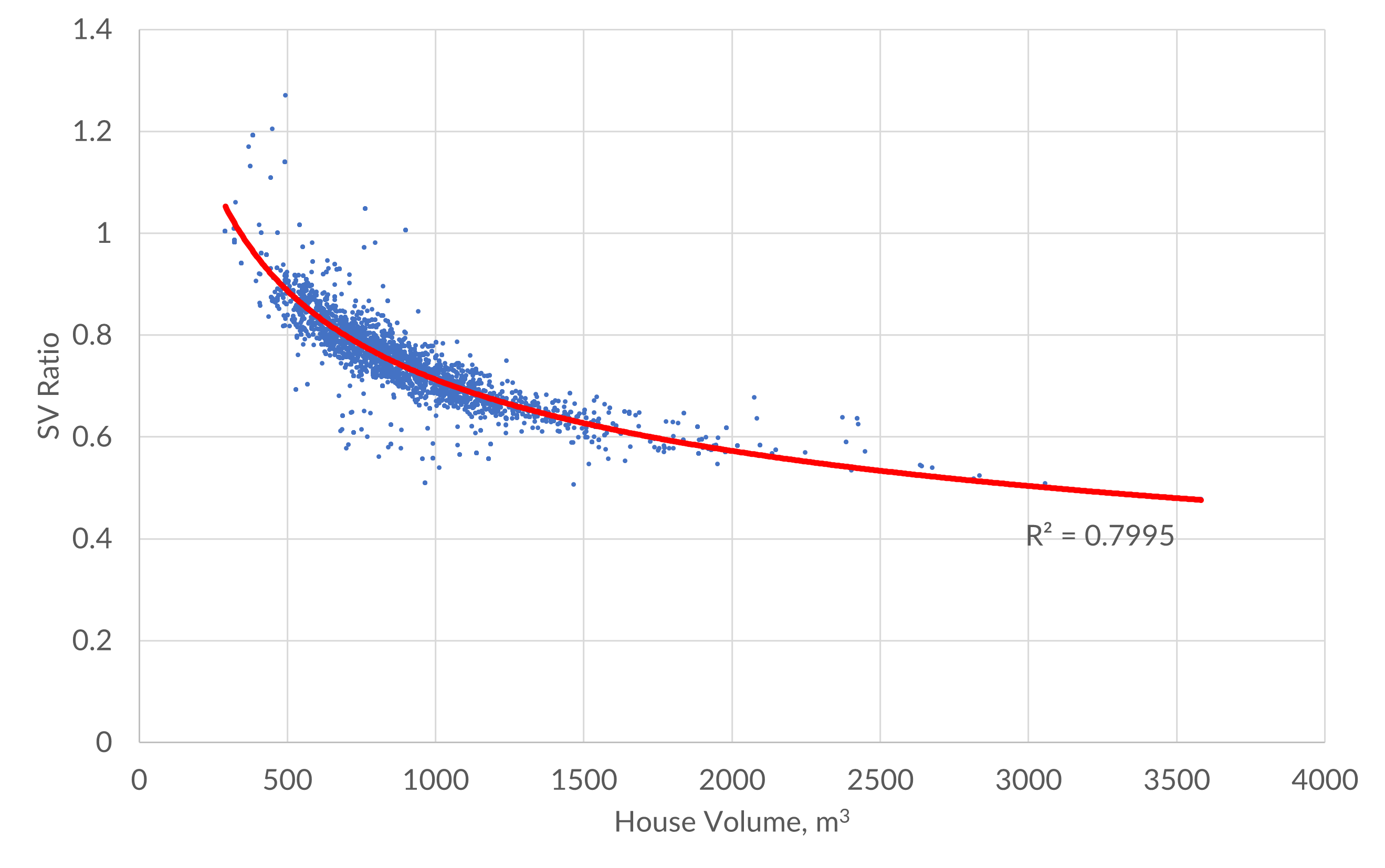
Impact on Houses with Different Forms and Geometries
In terms of impact on the form and geometry of housing, the SV of the house determines whether that particular house will achieve compliance more readily with either NLR50 or ACH50 metrics, when presented with targets in both metrics. When the SV is higher (typical of smaller houses), the NLR50 target is more readily achieved. Conversely, when the SV is lower (typical of larger houses), the ACH50 target is more readily achieved.
An analysis of the typical relationship of SV to house volume in 8117 homes in Ontario is shown in Figure 2. The data shows that as houses grow in size, they tend to have a lower SV.
Figure 2. SV trend by house volume
Currently, larger houses (with lower SV) comply more readily with required ACH50 targets, so the removal of this metric would require an improvement in the airtightness of assemblies for these houses. For example, if using an NLR50 target of 0.89L/(s×m2) (i.e., AL-1A) for a 1500m3 house with an SV of 0.62, the equivalent ACH50 target is 1.99. The reference house would also now use an ACH50 of 1.99 in this instance. This represents a 20.5% reduction in the targeted ACH50 value.
Conversely, smaller houses (with higher SV) currently comply more readily with NLR50 targets, so these houses would not require any improvement in the airtightness of assemblies to remain compliant. However, the impact would affect the reference house and, therefore, the relative impact of airtightness on energy performance. For example, if using the same NLR50 target of 0.89L/(s×m2) (i.e., AL-1A) for a 300m3 house with an SV of 1.02 (small compact house), the equivalent ACH50 is calculated as 3.27. In the NBC2020, the reference house still uses the ACH50 value of 2.5, meaning that the compliant house is compared against a reference house that is 23.5% more airtight. This proposed change would correct this misalignment and require that the reference house also use the equivalent ACH50 value of 3.27 in this case.
The use of NLR50 as the governing airtightness metric might require houses with lower SV (typically larger houses) to demonstrate improvements in building envelope airtightness compared to current requirements, while houses with higher SV (typically smaller houses) would be compared against a more appropriate baseline reference house.
This proposed change that aligns the airtightness requirements in the tiered performance path with those of the performance path in Section9.36. of NBC would
make consistent and simplify Section9.36.,
give meaning to performing an airtightness test by using the result, and
remove the significant cost burden associated with detached houses and moderate burden associated with attached houses of providing energy efficiency measures to compensate for the required use of the NLR50 value of 1.25L/(s×m2) instead of 0.89L/(s×m2) (detached houses) or 1.17L/(s×m2) (attached houses) where compliance with specific prescriptive requirements is demonstrated.
Enforcement implications
The proposed change could be enforced using existing Code enforcement infrastructure.
Some training and education may be required for authorities having jurisdiction as they will need to be familiar with the NLR50 metric if they are not using it already on a regular basis.
Who is affected
Designers, engineers, architects, building officials, manufacturers, suppliers and energy advisors.
OBJECTIVE-BASED ANALYSIS OF NEW OR CHANGED PROVISIONS