This proposed change updates the thermal bridging requirements in the NECB to reflect new modeling and standards.
Problem
The performance of the building envelope is a key contributor to the energy performance of the building. A thermal bridge occurs when a component of the building envelope conducts heat from the exterior to the interior of the building or vice-versa. Moisture condensation, thermal discomfort and excessive energy use can result.
Sentence 3.1.1.5.(5) of Division B of the National Energy Code of Canada for Buildings (NECB) does not currently include a referenced standard for two- or three-dimensional thermal simulation. Clear direction for Code users should be provided to perform this modeling.
Sentence 3.1.1.7.(3) excludes the thermal bridging effects due to fasteners from the calculation of thermal transmittance through the building envelope. This is problematic as the effects of thermal bridging result in excessive energy use.
There are misalignments between the NECB and National Building Code of Canada (NBC) Section 9.36. in regard to the calculation of thermal resistance, which could make demonstrating compliance more difficult for Part 9 buildings where the option is given of complying with either Code. If NBC Section 9.36. and the NECB have different requirements, this causes confusion for Code users.
The absence of appropriate and accurate methods of calculation for thermal bridging will result in energy loss not being accounted for, which in turn leads to Code users not achieving the expected energy savings and also leads to excess energy use, which would have an unacceptable effect on the environment.
Justification
This proposed change accounts for the energy lost due to thermal bridging and requires that the loss be compensated for by another component of the building envelope.
This proposed change also updates the referenced standards in the Code to include CSA Z5010:21, “Thermal bridging calculation methodology,” as a method of modeling thermal bridging using two- or three-dimensional thermal simulation. This calculation method allows for a more accurate determination of heat loss at junctions. And, ASTM C1199-22, “Standard Test Method for Measuring the Steady-State Thermal Transmittance of Fenestration Systems Using Hot Box Methods,” is also introduced as an acceptable method to determine the thermal properties of fenestration.
Review of both standards determined that:
there are no issues in the standards falling outside the scope and application of the NBC and the NECB,
there are no inconsistencies between the definitions used in the standards and those used in the NBC and the NECB,
there are no new or revised definitions that would need to be added to the NBC and the NECB,
the standards address minimum acceptable practice,
CSA Z5010 addresses issues that need to be regulated by providing a calculation guideline for thermal bridging,
ASTM C1199 addresses issues that need to be regulated by providing a test method for the energy performance of fenestrations and is equivalent to ASTM C1363 but it is specifically for fenestration and will provide a more accurate result,
referencing the standards does not necessitate the creation of a new objective or functional statement,
referencing the standards causes no additional cost implications, and
the standards should be referenced without limitations/qualifications.
This proposed change also harmonizes the requirements between the NECB and NBC Section 9.36. If NBC Section 9.36. and the NECB were to have different requirements, confusion would be caused for Code users, as compliance with the NECB is an option for NBC Part 9 buildings. Harmonizing the NECB and NBC Section 9.36. facilitates compliance for Code users.
Using appropriate and accurate methods for the calculation of thermal bridging will result in accurate energy loss accounting. As a result, Code users would achieve the expected energy savings, and excess energy use would also be prevented.
PROPOSED CHANGE
NECB20 Div.B 3.1.1. (first printing)
[3.1.1.] 3.1.1. General
[3.1.1.1.] 3.1.1.1.Scope
[3.1.1.2.] 3.1.1.2.Application
[3.1.1.3.] 3.1.1.3.Compliance
[3.1.1.4.] 3.1.1.4.Definitions
[1] 1)Words that appear in italics are defined in Article 1.4.1.2. of Division A.
[2] --)For the purposes of this Part, the term “thermal bridge” shall mean a point, linear area or surface area of a building envelope that has a thermal transmittance higher than the nominal thermal resistance of an adjacent building envelope assembly, which results in a higher energy flow through the point, linear area or surface area and increases the risk of condensation. (See Note A-3.1.1.4.(2).)
[3.1.1.5.] 3.1.1.5.Thermal Characteristics of Building Assemblies
[1] 1)The thermal characteristics of building envelope materials shall be determined in accordance with the applicable product standards listed in the NBC or, in the absence of such standards or where such standards do not address the determination of thermal characteristics, in accordance with
[a] a)ASTM C177, "Standard Test Method for Steady-State Heat Flux Measurements and Thermal Transmission Properties by Means of the Guarded-Hot-Plate Apparatus",or
[b] b)ASTM C518-21,"Standard Test Method for Steady-State Thermal Transmission Properties by Means of the Heat Flow Meter Apparatus",or
[c] --)ASTM C1363-19, “Standard Test Method for Thermal Performance of Building Materials and Envelope Assemblies by Means of a Hot Box Apparatus.”
[2] 2)Calculations and tests performed in accordance with Sentence (1) shall be carried out at an average temperature of 24±2°C and under a temperature difference of 22±2°C.
[3] 3)Except as provided in Sentence (4), the overall thermal transmittance of fenestration and doors shall be determined for the reference sizes listed in accordance with
[a] a)CSA A440.2:22/CSA A440.3:22, "Fenestration energy performance/User guide to CSA A440.2:22, Fenestration energy performance,"CSA A440.2/A440.3, "Fenestration energy performance/User guide to CSA A440.2:19, Fenestration energy performance", or
[b] b)ANSI/NFRC 100-2020,"Procedure for Determining Fenestration Product U-factors",and ANSI/NFRC 200-2020 “Procedure for Determining Fenestration Product Solar Heat Gain Coefficient and Visible Transmittance at Normal Incidence.”
[4] 4)The overall thermal transmittance of fenestration and doors that are not within the scope of the standards listed in Sentence (3) shall be determined from
[a] a)calculations carried out using the procedures described in the 2021"ASHRAE Handbook – Fundamentals", or
[b] b)ASTM C1199-22, “Standard Test Method for Measuring the Steady-State Thermal Transmittance of Fenestration Systems Using Hot Box Methods.”laboratory tests performed in accordance with ASTM C1363, "Standard Test Method for Thermal Performance of Building Materials and Envelope Assemblies by Means of a Hot Box Apparatus", using an indoor air temperature of 21±1°C and an outdoor air temperature of –18±1°C measured at the mid-height of the fenestration or door.
[5] 5)The thermal characteristics of building assemblies other than fenestration and doors shall be determined from
[a] a)calculations carried out using the procedures described in
[i] i)the 2021"ASHRAE Handbook – Fundamentals",or
[ii] ii)ISO 14683:2017,"Thermal bridges in building construction – Linear thermal transmittance – Simplified methods and default values",or
[b] b)two- or three-dimensional thermal modeling, or
[c] c)laboratory tests performed in accordance with ASTM C1363-19,"Standard Test Method for Thermal Performance of Building Materials and Envelope Assemblies by Means of a Hot Box Apparatus", using an indoor air temperature of 21±1°C and an outdoor air temperature of –18±1°C.
[6] --)The thermal characteristics of log walls shall be determined by calculation in accordance with Section 305 of ICC 400-2017, ”Standard on the Design and Construction of Log Structures.” (See Note A-3.1.1.5.(6).)
[3.1.1.6.] 3.1.1.6.Calculation of Fenestration and Door Areas
[1] --)The gross ceiling or roof area shall be calculated as the sum of the interior surface areas of insulated ceiling and/or roof assemblies and of skylight openings.
[2] --)The gross wall area shall be calculated as the sum of the interior surface areas of all exterior building envelope assemblies above the finished ground level, including
[a] --)rim joists,
[b] --)fenestration and doors,
[c] --)insulated walls extending from finished ground level to the interior side of the insulated ceiling and/or roof assembly, and
[d] --)the exposed areas of below-ground building envelope assemblies, where fenestration or doors are located below the plane of the adjacent finished ground.
(See Note A-3.1.1.6.(2)-2025.)
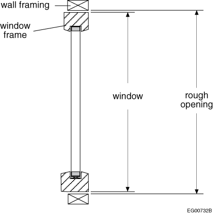
[3] 1)Fenestration and door areas shall be calculated to the rough opening in the wallactual size of the fenestration and doors, and shall include all related frame and sash members. (See Note A-3.1.1.6.(1)PROPOSED CHANGE A-3.1.1.6.(1).)
[4] 2)The fenestration area made of flat panes that are not all in the same plane or curved panes shall be measured along the surface of the glass. (See Note A-3.1.1.6.(42)Note A-3.1.1.6.(2)PROPOSED CHANGE A-3.1.1.6.(2).)
[5] 3)Except as provided in Sentence (4), in the calculation of allowable fenestration and door area, the gross wall area shall be calculated as the sum of the areas of all above-ground wall assemblies including fenestration and doors, but not including parapets, projected fins, ornamentation and appendages.
[6] 4)The calculation of allowable fenestration and door area in additions shall be based upon
[a] a)the addition being considered by itself, or
[b] b)the addition being considered together with the existing building, provided that the combined overall thermal transmittance of the addition and existing building meets the prescriptive or trade-off requirements.
[7] 5)In the calculation of allowable skylight area, the gross roof area shall be calculated as the sum of the areas of insulated roof including skylights.
[3.1.1.7.] 3.1.1.7.Calculation of Overall Thermal Transmittance
[1] 1)In calculating theFor the purpose of compliance with this Part, the calculatedoverall thermal transmittance of opaque assemblies for purposes ofcomparisonwith the provisions in Section 3.2.,shall include the effect of thermal bridging shall be considered for all elements of the assembly, including
[a] a)point thermal bridges,closely spaced repetitive structural members, such as studs and joists, and ancillary members, such as lintels, sills and plates,
[2] 2)In calculating the overall thermal transmittance of the assemblies in Sentence (1) for purposes of comparisoncompliance with the provisions in this PartSection 3.2., pipes, ducts, equipment with through-the-wall venting, packaged terminal air conditioners or heat pumpspenetrations through the assemblies by components of the building’s mechanical, electrical and plumbing systems need not be taken into account. (See Note A-3.1.1.7.(2)PROPOSED CHANGE A-3.1.1.7.(2).)
[3] 3)In calculating the overall thermal transmittance of assemblies for purposes of comparison with the provisions in Section 3.2., fasteners need not be taken into account.
[4] 4)Where a component of the building envelope is protected by an enclosed unconditioned space, such as a sun porch, enclosed veranda or vestibule, the unconditioned enclosure may be considered to have an overall thermal transmittance of 6.25 W/(m2×K). (See Note A-3.1.1.7.(4)PROPOSED CHANGE A-3.1.1.7.(4).)
[5] 5)For the purposes of this Article, roof assemblies shall be considered to include all related structural framing.
[6] 6)For the purposes of this Article, wall assemblies inclined less than 60° from the horizontal shall be considered as roof assemblies, and roof assemblies inclined 60° or more from the horizontal shall be considered as wall assemblies.
[7] 7)For the purposes of this Article, wall assemblies shall be considered to include all related structural framing and perimeter areas of intersecting interior walls.
[8] 8)For the purposes of this Article, floor assemblies shall be considered to include all related structural framing.
Note A-3.1.1.4.(2)Condensation Risk for Thermal Bridges.
The inner surface temperature of the point, linear area or surface area that acts as a thermal bridge in an assembly can be significantly colder than the surrounding area. This difference in temperature can lead to condensation on the thermal bridge if its surface temperature is colder than the dew point of the surrounding air. Such condensation can, in turn, lead to the degradation of materials, components and assemblies, and to the growth of mould.
Note A-3.1.1.5.Thermal Characteristics of Building Assemblies.
Thermal characteristics of building assemblies can also be determined through the use of computer simulation models. Examples of software tools include THERM, WINDOW, COMSOL and Siemens NX.
Methods for calculating the effect of thermal bridging for common scenarios are available, as are databases and catalogues of pre-calculated or measured results. For instance,Acceptable sources of information for calculating the effect of thermal bridging are the "Building Envelope Thermal Bridging Guide", which is available through BC Hydro or the Licensing and Consumer Services branch of BC Housing, and ASHRAE Research Project Report RP-1365, "Thermal Performance of Building Envelope Details for Mid- and High-Rise Buildings".. Also, an online energy calculator for roofs, Energy-RCI, is available at: https://nrc.canada.ca/en/research-development/products-services/software-applications/energy-rci.
Note A-3.1.1.5.(6)Calculating Effective Thermal Resistance of Log Walls.
ICC 400, “Standard on the Design and Construction of Log Structures,” defines log wall thickness as the “average cross-sectional area divided by the stack height.” This approach equalizes all log profiles regardless of their size or shape by eliminating the need to vary, average or round out log thickness measurements, which would otherwise be necessary to determine applicable profile factors for different log shapes. ICC 400 lists R-values for log walls, including the exterior and interior air film coefficients, based on wall thickness and wood species' specific gravity.
Note A-3.1.1.6.(1)Fenestration and Door Areas.
The method of calculation of fenestration and door areas is slightly different in Sentence 3.1.1.6.(1) from the one used in CSA A440.2/A440.3, "Fenestration energy performance/User guide to CSA A440.2:19, Fenestration energy performance", for windows and doors. For calculating the fenestration area of a building, this Code uses the dimensions of rough openings to facilitate determination of compliance.
Figure A-3.1.1.6.(1) illustrates the requirements of Sentence 3.1.1.6.(1).
Figure [A-3.1.1.6.(1)] A-3.1.1.6.(1) Measuring fenestration and door areas
Where the structure of the lowest floor and rim joist assembly is above the finished ground level or where the above-grade portion of foundation walls separates conditioned space from unconditioned space, they should be included in the calculation of gross wall area. Figure A-3.1.1.6.(2) shows the intended measurements for the most common type of housing construction.
Figure [A-3.1.1.6.(2)-2025] Example of interior wall height to be used in the calculation of gross wall area
Note A-3.1.1.6.(42)Areas of Other Fenestration.
Figure A-3.1.1.6.(2) illustrates how to measure the area of glass panes as described in Sentence 3.1.1.6.(2).
Figure [A-3.1.1.6.(42)] A-3.1.1.6.(2) Measuring areas of glazing that is not in the same plane
Note A-3.1.1.7.(1)-2025Linear Elements, Point Elements and Junctions.
Point elements include fasteners (however, fasteners that do not penetrate the insulation layer do not need to be accounted for in the calculation), ties, anchors, attachments and connectors.
Linear elements include studs, joists, ancillary members, lintels, plates, sills, flashings, angles, shelf angles, purlins, girts, sub-girts, hat channels, U-channels and furring.
Junctions between building envelope materials, components and assemblies occur at balconies, canopies, slab edges, fenestration perimeters (including the installation design details between the rough opening and the fenestration), spandrels, parapets, roof-to-wall junctions, corners, and edges of walls or floors. Junctions also occur at the intersection of interior walls with exterior walls, roofs or ceilings.
Note A-3.1.1.7.(1)(b)Major Structural Elements.
Examples of major structural elements that could penetrate the building envelope are walls, floors, roofs, balconies, joists, beams, girders, columns, and curbs.
Secondary structural members typically attach cladding elements to primary structural members. Examples of secondary structural members are girts, purlins, sub-girts, hat-channels, U-channels, and shelf angles.
Note A-3.1.1.7.(2)Penetrations through the Building Envelope.
Examples of the penetrations described in Sentence 3.1.1.7.(2) include pipes, ducts, equipment with through-the-wall venting, and packaged terminal air conditioners or heat pumps. The impact of such penetrations described in Sentence 3.1.1.7.(2) on the overall thermal transmittance is difficult to assess but is considered to be negligible if the insulation is installed tight to the penetration.
NECB20 Div.B 3.2.1.2.(2) (first printing)
[3.2.1.2.] 3.2.1.2.Continuity of Insulation
[1] 2)Joints between components of the building envelope, such as expansion or construction joints or joints between walls and doors or fenestration, shall be insulated in a manner that provides continuity across such joints. (See Note A-3.2.1.2.(2)PROPOSED CHANGE A-3.2.1.2.(2).)
Note A-3.2.1.2.(2)Continuity of Insulation Where Components Meet.
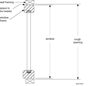
Sentence 3.2.1.2.(2) calls for continuity of the insulation at the intersection of two components of the building envelope, such as a wall with another wall or a roof, or a wall with a window. This means that there should be no gap in the insulation between the two components. An obvious application is insulating the space between a window or door frame and the rough framing members. For example, to reduce thermal bridging, the space between the window frame and the rough opening in the wall framing (shown in Figure A-3.2.1.2.(2)), may be treated with low-expansion sealant foam product complying with CAN/ULC S710.1:2019, “Standard for Bead-Applied One Component Polyurethane Air Sealant Foam, Part 1: Material Specification,” or CAN/ULC S711.1:2019, “Standard for Bead-Applied Two Component Polyurethane Air Sealant Foam, Part 1: Material Specification.”
Figure [A-3.2.1.2.(2)] Space between window frame and rough opening in wall framing
Impact analysis
Roofing Analysis
Using the highest density of roofing fasteners the thermal transmittance of the assembly was calculated and is shown in Table 1. The highest density was selected as a worst-case scenario.
Table 1. Thermal Transmittance of the Roofing Assembly
Climate Zone
NECB 2020 Transmittance (W/m2K)
Current R
Fastener Factor %
Transmittance with Fasteners (W/m2K)
4
0.164
34.6
15.5
0.189
5
0.156
36.4
16.2
0.181
6
0.138
41.1
18.1
0.163
7a
0.121
46.9
20.3
0.146
7b
0.117
48.5
21
0.142
8
0.11
51.6
22.2
0.134
The updated thermal transmittance values were applied to three archetypes in six locations. The difference in overall building energy use intensity (EUI) is shown in Table 2.
Table 2. Difference in Overall Building EUI
Building
Location
EUI with Fasteners
EUI without Fasteners
% diff
Retail Standalone
Edmonton, AB
165.5
162.3
2.0
Victoria, BC
149.2
147.2
1.4
Yellowknife, NT
239.3
234.2
2.2
Windsor, ON
172.3
170
1.4
Montréal, QC
177.2
174.6
1.5
Whitehorse, YT
189.5
185.6
2.1
Secondary School
Edmonton, AB
172.5
170.7
1.1
Victoria, BC
137.6
136.6
0.7
Yellowknife, NT
275.5
272.7
1.0
Windsor, ON
166.5
165.3
0.7
Montréal, QC
178.6
177.1
0.8
Whitehorse, YT
210.3
208.1
1.1
Warehouse
Edmonton, AB
120.6
117.6
2.6
Victoria, BC
94.44
92.77
1.8
Yellowknife, NT
178.4
173.9
2.6
Windsor, ON
135.6
133.6
1.5
Montréal, QC
141
138.6
1.7
Whitehorse, YT
142.7
139.2
2.5
As can be seen, the effect of including the thermal bridging of roofing fasteners in the thermal transmittance calculation increases the overall building EUI by up to 2.6%. A lesser difference is expected in buildings with smaller roof areas (compared to their volume). For this reason, the impact of roofing fasteners that penetrate the insulation layers should be included in the calculation of effective thermal transmittance.
Wall Fasteners
The effect of including wall fasteners in the thermal transmittance calculation was examined for both the NECB and the NBC with respect to changes in the overall thermal transmittance of the envelope. For wood-framed walls with cavity insulation the change in thermal transmittance was less than 1.2%; where no cavity insulation was included, the change increased to 3.3% maximum.
For steel-framed walls, transmittance increased by up to 2.3% for walls with cavity insulation and up to 2.5% for walls without cavity insulation.
An increase in transmittance of 2.5% would result in an incremental cost of approximately $0.30/ft.2 in all regions in Canada. Cost data is sourced from RSMeans (accessed in June 2023).
Overall Effect
These are relatively minor changes in thermal transmittance so it is expected that the overall effect at the building level would be minor, with an increase in EUI of less than 5% when accounting for both roof and wall fasteners.
For simplicity in the Codes, this proposed change includes the effect of wall fasteners that penetrate insulation (without distinguishing between a wall and a roof) despite the effect being small; the analysis may have overlooked cases where the fastener is important (110 wall scenarios were examined).
For the analysis method and data source used, see "Wall U-Values" and "Roofing R-Values" attached as supporting documents.
Enforcement implications
This proposed change would require no changes to Code enforcement as no change to design is being proposed.